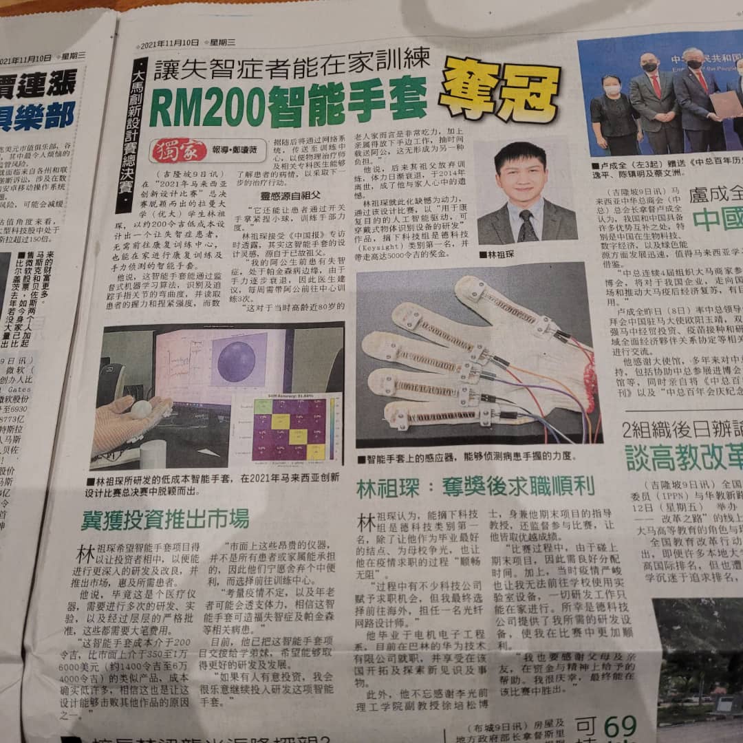
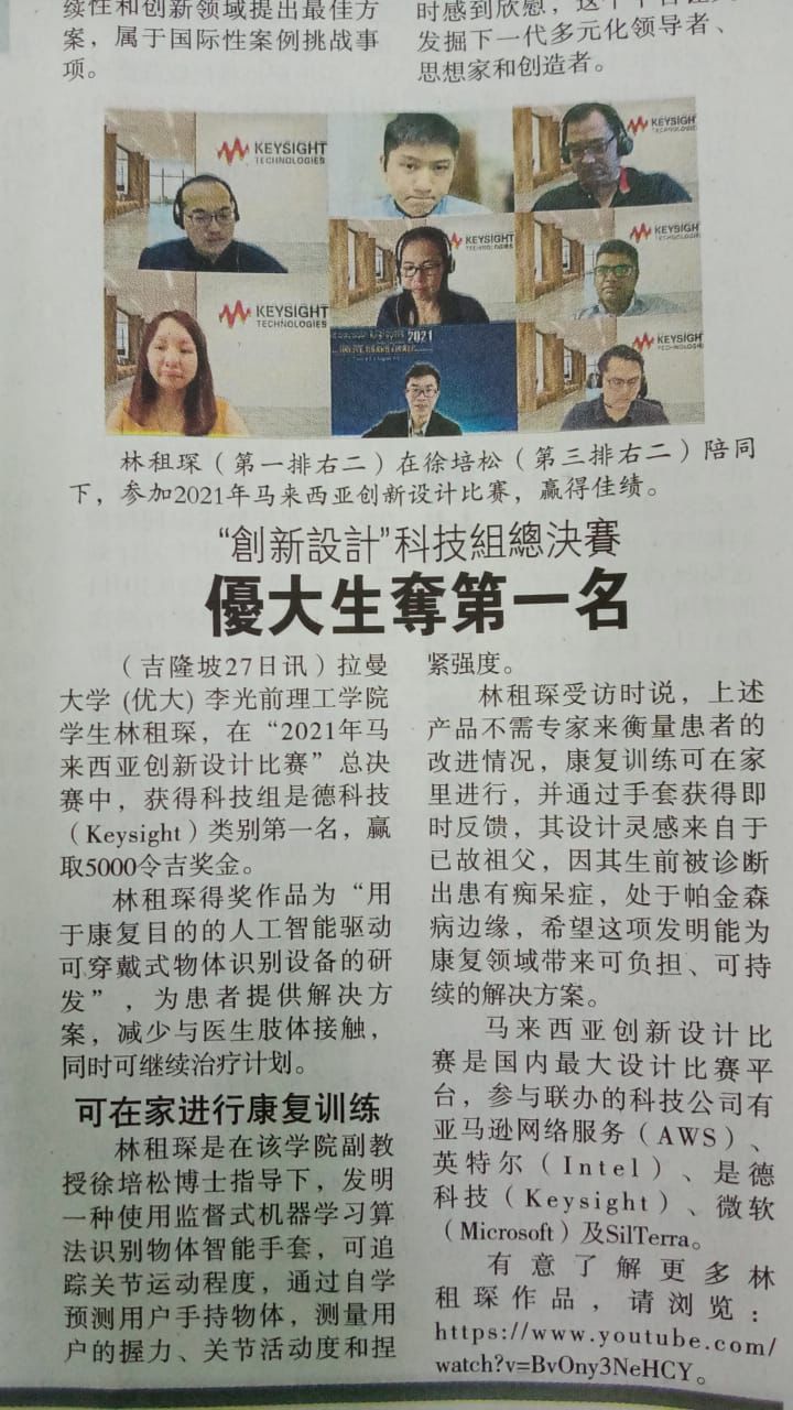
EDIT: This project won first place in the Innovate Malaysia Design Competition 2021 (IMDC 2021), the largest design competition in Malaysia with over 274 submissions from universities throughout the country. It was featured in my university’s website and also in multiple national news outlets including the China Press, Sin Chew Daily, and Nangyang Business Daily.
Introduction
Note: this project write-up is a condensed version of my research, for full research please refer to my Github link
During the final year of my bachelor’s degree, as a prerequisite to graduation, I was required to complete a final year project (FYP) as a way to gauge the research and practical skills that I’ve obtained throughout the years in the university.
As such, the research topic for my FYP was to design and fabricate a wearable electronic prototype equipped with an AI algorithm. The topic of this research was deliberately made open ended to allow for flexibility and creativity in the proposed solution and the problems it solves.
My proposed solution was to design a prototype for a wearable smart glove equipped with a machine learning model capable of recognizing the shapes of objects through resistive based flex sensors attached on each finger.
Purpose
The purpose of this project was to target the sector of remote monitoring for the rehabilitation of patients where hand motor functions are affected. This includes post-stroke patients or patients with neurodegenerative diseases such as Parkinson’s disease. This glove aims to assist by providing rehabilitation exercise data such as finger joint bending angle, improvement of finger joint movement over time and providing recommended hand exercises to rehabilitate specific hand-movement injuries. Moreover, the data obtained by the glove can also be sent remotely to a physiotherapist to gauge the progress of their patients.
Process
This section contains all the technicalities of the project, including the hardware and the software explanations. For those only interested in the results of this project, please scroll down to the next section.
Sensor Characterization
Before any software or hardware is implemented, I first have to characterize the flexible resistive sensor to ensure that I have an accurate estimation on how much the resistance changes in reference to the finger joint angle. To do that, I designed a very simple circuit to measure the analog voltage given a fixed input voltage.
This circuit is essentially a voltage divider with an op-amp set to a voltage follower to reduce the input impedance of the flex sensor. The resistance change within the flex sensor will cause a change in output voltage, Vout according to the voltage divider rule, where Vout = (R1/(R1+R2))*Vin.

Once the circuit is implemented, Vout is connected to an Arduino to read the output voltage. The output voltage can then be converted to resistance via the formula above.


From the graph below, it is clear that the full range of the index finger movement corresponds to a change in resistance that ranges almost linearly with a resistive sensitivity of 0.0145 kΩ/° .

Hardware design
Once the characterization is completed and I fully understood the behavior of the resistive sensors, it was time to design and prototype the hardware solution for this project.
When designing for the hardware part, I knew that I had to find some ways to attach the sensors as close as possible to my fingers to get the most accurate finger angle reading. To do that, I had chose to use a simple cotton gardening glove. This turned out to be a great choice compared to other types of glove (fabric, leather) as it provided a few advantages:
- Gardening gloves are very common and can be bought at almost any hardware store inexpensively.
- Gardening gloves are also elastic, fitting the hand snugly to allow for the resistive sensors to be as close to the fingers as possible.
- Can be easily modified by sewing and/or gluing.
To attach the sensors to the glove, I designed and 3D-printed some strain relieve clamps to fix the sensors in place and to provide strain relieve when the sensor is bent. A total of 5 sensors are attached on the glove, one for each finger. The sensors are sewn to the glove tightly lengthwise to ensure that the sensor is as close to the finger as possible.
Training Data Acquisition
Once the hardware prototype was made, I started collecting training data for the machine learning algorithm. The machine learning training was done on three sample objects: a sphere, a cuboid, and a cylinder. The objects are designed in a CAD software and 3D printed to ensure dimensional accuracy.
The training data is obtained by wearing the glove, pushing a push button connected to an Arduino to enable data logging, picking an object up and releasing it to form a dynamically changing time-series graph. Each sample consists of 150 data points, and each object was sampled 200 times for a total of 30,000 data points for each object. The samples are then labelled to the shape of the object it belongs to and exported to a CSV file format with a distinct name to allow for easy debugging and file navigation in the training stages.
SVM Model Training

After obtaining the training data for the three objects, an Support Vector Machine (a type of Machine Learning algorithm) classifier is implemented using Python’s scikit-learn library. The data is split into two sets: a test set and a train set. The data in the train set is used to fit the SVM model and hence will contain a majority of the data sample; while the data in the test set is used to provide an unbiased evaluation of the performance of the model. In my case, the train-test set was split by 80% and 20%, respectively. The data was also stratified. The test-train sets consisted of evenly distributed labelled data of each object to prevent a biased prediction. The fitted SVM classifier can then be used to predict an object’s shape on a real-time basis.
Results
The confusion matrix of the SVM models in the figure below shows that this artificial intelligence model can assist the glove in achieving more than 91% accuracy in recognizing the shape of objects. The kernel parameter, C, which is used to determine the possibilities of misclassification, was remained at the default and not optimized. Each object has 160 training samples and a testing sample of 40 samples (80% to 20% split). The baseline (not holding any objects) has a 100% prediction rate and the highest error appears to be the cuboid with 82.5% true predictions with 7 samples being predicted wrongly. This can be attributed to the lack of training samples and the accuracy might increase with higher training samples.

The real-time prediction of the glove was also realized by incorporating real-time input from the sensor into the trained SVM model. A button is pushed, sending a signal to the Arduino to start reading the sensor output and transmitting it to the Python program via serial communication. The SVM then takes the input data, parses it, and makes a prediction based on the trained samples. There are four possible outputs depending on the inputs, as shown below.


