SMD Reflow Hot Plate

Introduction

Recently I’ve been trying to get myself into PCB fabrication using surface mount components to reduce the size of my prototype. Since I do not own a hot air rework station, it has been very difficult for me to solder surface mount components (SMD) by using a handheld soldering iron. Not only that, removing surface mount components are almost impossible using a handheld soldering iron because there are multiple points that has to be heated at the same time to remove the component. Therefore, I wanted to build myself a simple DIY SMD soldering station.

Methods and Results

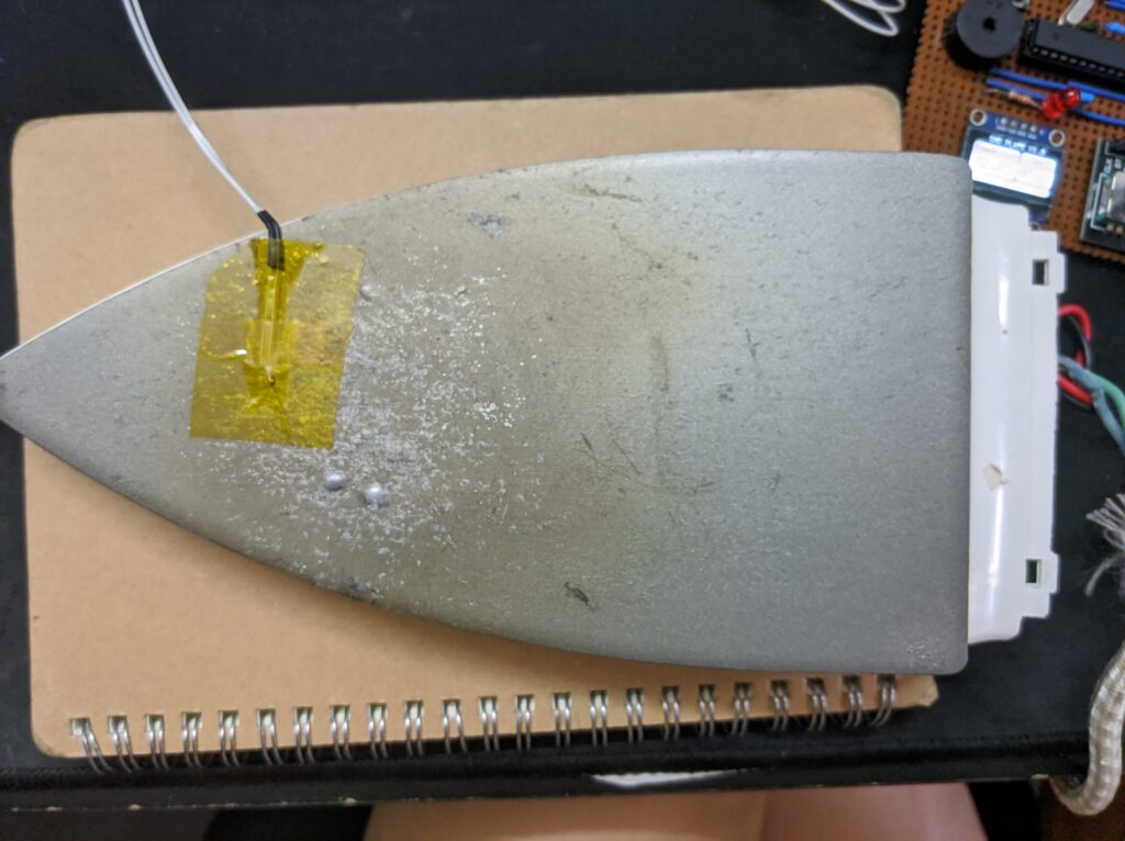
As always, I started by researching on the different methods of soldering SMD parts. I came across this guide that tried out most of the methods of SMD soldering. From that article, the hot-plate reflowing was one of the cheaper and more effective methods. However, instead of using a skillet (like from the article), I had an old flat clothes iron laying around which I thought could be a great upcycling opportunity. Time to start the disassembly process!
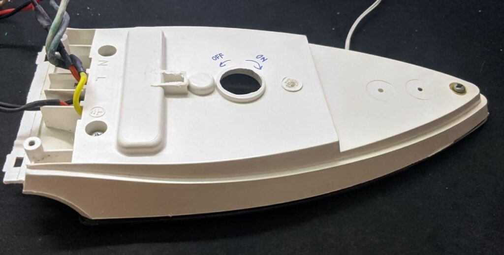
Clothes iron disassembled and unwanted parts cut off to make the back flat

The disassembly of the iron was quite straightforward. I had to remove a thermal fuse from the iron as the reflowing temperature will exceed the fuse’s rated temperature. The rest of the circuit was kept as intact as possible.

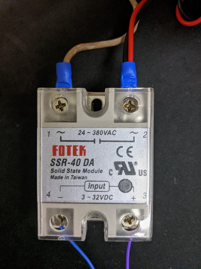
My plan was to add a simple temperature-controlled system to the iron by using a relay to switch the iron on and off and a temperature sensor as a feedback to the microcontroller. So I started a breadboard prototype using an Arduino Uno, a thermistor, and a solid-state relay.

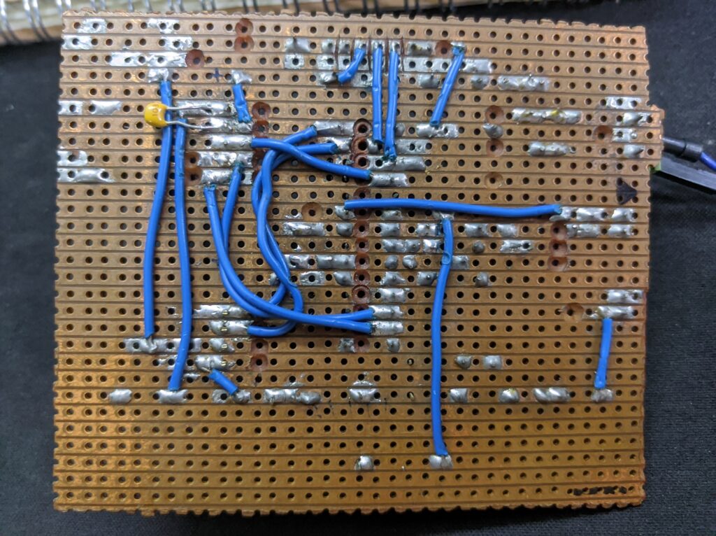
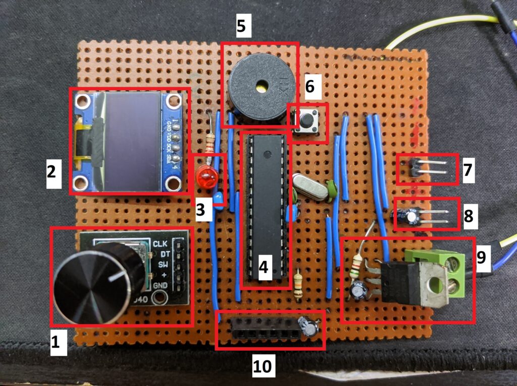
Once I have the basic functionality programmed and tested, I designed and hand-soldered a pcb with the ATMEGA328P as the microcontroller.

The components labelled in the picture above are as follows:

  1. Rotary Encoder
  2. 0.96″ OLED Display
  3. Relay Trigger Indicator
  4. ATMEGA328P Microcontroller
  5. Buzzer
  6. Reset Button
  7. Relay Header
  8. Thermistor Header
  9. 5V Regulator
  10. FTDI Header

The PCB is designed with a program reset button and an FTDI header to upload newer versions of the program. The temperature can be set by clicking the rotary encoder and rotating the knob. The red LED is an indicator light to show when the heater element is turned on. Double clicking the rotary encoder will allow for a preset temperature (set in the program) and a long press of the encoder will fully turn off the relay. After some iterations of the program, this is what I’ve ended up with:

By combining a relay and thermistor to the PCB and some addition of the code, I now have a working SMD reflow plate!

Once all of that was done, it was time to test solder an SMD LED and a 4020 package resistor. I initially set the plate to around 180°C as recommended by the manufacturer of the soldering paste. However, through multiple tests, I found out that that temperature is too low and it takes a very long time to turn the solder into a shiny blob of metal. This may be because the plate has to heat the bottom of the PCB and the heat has to transfer to the top of the PCB before melting the solder. In addition, PCB’s are not completely flat which means there is an air gap between the hot plate and the PCB. This causes the air to act as an insulation layer thus increasing the time needed to fully melt the solder.

Through several testing, I found that the optimal temperature for this hot plate is around 220-230°C. The full soldering process takes around 5 minutes (excluding adding the paste). I’m quite proud of how this turned out!

How It Works

The working principle of this system is actually pretty straightforward: the user will give a set temperature for the hot plate to achieve, the program will compare the current temperature with the set temperature. If the set temperature is higher than the current temperature, the relay turns on and vice versa. Although this is not the most accurate way of controlling the temperature (there will be oscillations caused by the thermal inertia of the iron), a threshold based system is the simplest way to achieve temperature control.

As the iron had a 1000W rating, the iron heated up too quickly and the thermal inertia of the iron caused the thermistor to react too slowly. This caused the iron to reach up to 270C with a set-point of 180C even after the relay switched off the iron. To prevent this, I had to limit the power consumption of the iron by implementing PWM switching. I had to lower the duty cycle to allow for only 20% of the max power to ensure that the iron does not heat up too quickly. A PID loop could be implemented to fix the aforementioned problem but limiting the power seemed to solve the issue so I didn’t bother to add a PID element. From there, it was a case of getting the Oled display, buzzer and a rotary encoder to act as an interface for the entire system.

A lot of time was spent debugging the PCB as the microcontroller and rotary encoder didn’t work correctly. I later found out this was caused by an unstable input voltage due to a noisy input voltage bus. However, that issue was fixed by adding decoupling capacitors close each of the input voltage on the microcontroller and the rotary encoder.

Conclusion

Overall, this project took me close to two months of on-and-off coding and debugging to complete. I’m really happy with how it turned out, and the next step is to add a base to attach all the components to. As always, the code to this project is completely open source and can be accessed from my Github project page. Thanks for reading!

IoT Enabled Smart Shelf

In my third-to-fourth year of my bachelor’s degree, it is compulsory for my course to take a capstone course, called an Integrated Design Project. It is a project that spans over two semesters, and gives us the opportunity to demonstrate the knowledge and skills that we’ve learnt throughout our studies. It is different from a Final Year Project, as this is a group-based work.

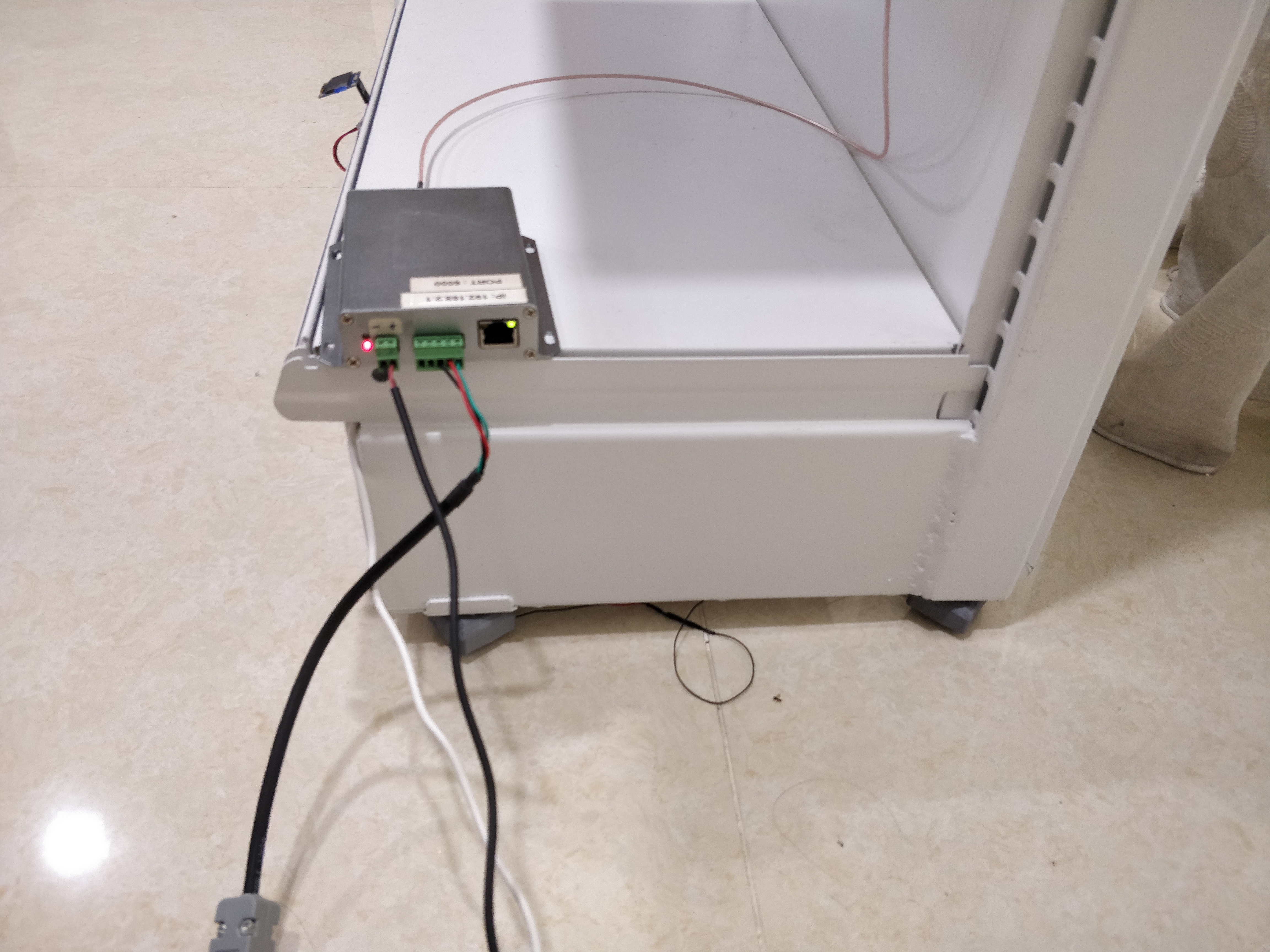
In my group’s case, at the supervision of our group’s supervisor Dr Chang, we were requested by a company in Sri Kembangan, Selangor which specializes in manufacturing Gondola shelves and supermarket racks to provide a smart shelving system which is able to calculate the remaining stock on the shelf and logs them in a real-time basis. The requirement by the company was that we weren’t allowed to use any cameras to track stock movement. We had about seven months to design and implement a prototype, as well as complete a proposal and a presentation for our solution. A total of four of us, with me leading the Hardware and Software implementation of the shelf, started work as soon as was possible.

Once we found out the size of our prototype shelf, we came up with two solutions to our design; by using a weight sensor and an RFID reader. The two solutions that we provide is to allow for a pros and cons comparison between them. Once all the electronics have arrived, I started to work on the hardware and software designs for our prototype.

Mini shelf sponsored by our client for our prototype

Weight Sensor System

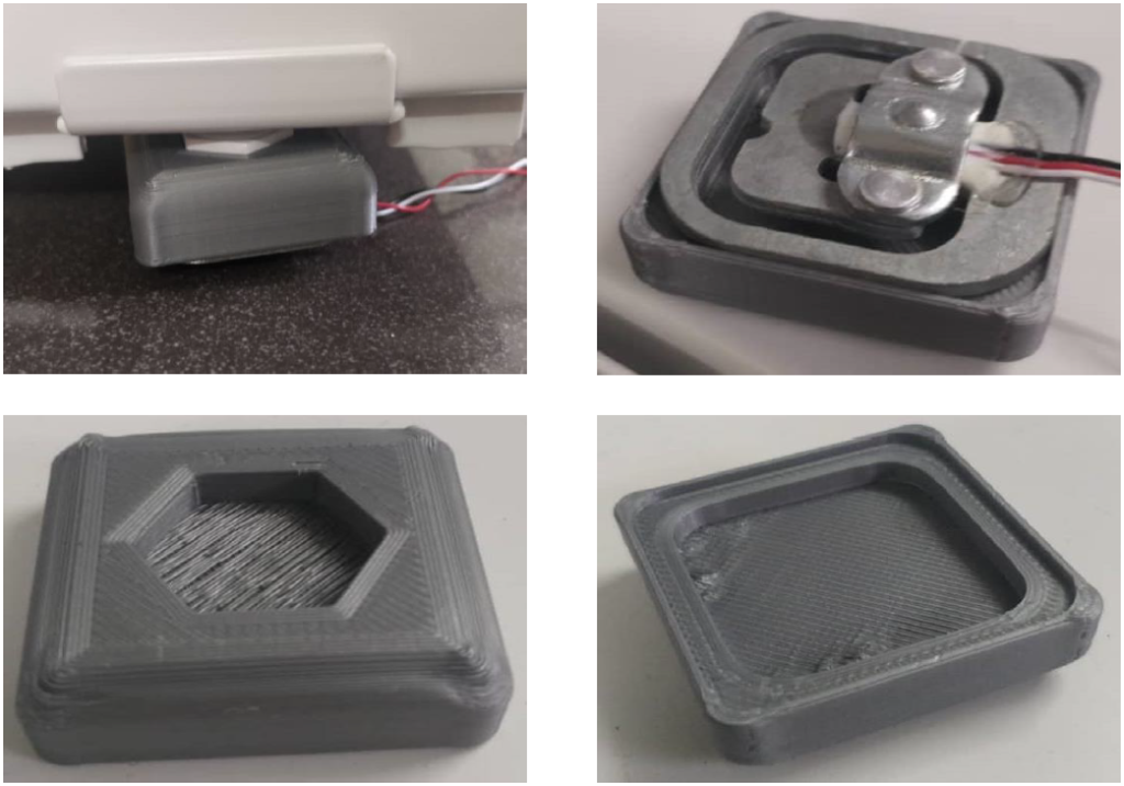
Firstly, I had to figure out how to attach the weight sensor onto the shelf. The four corners that’s holding up the entire shelf is screwed in with M.6 hex bolts and the weight sensors couldn’t fit on. Therefore, I had to design and 3D print an attachment part that allows for a snug fit between the weight sensor and the shelf. The parts are designed in Autodesk Fusion 360.

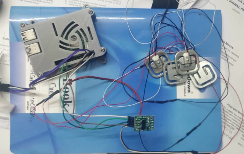
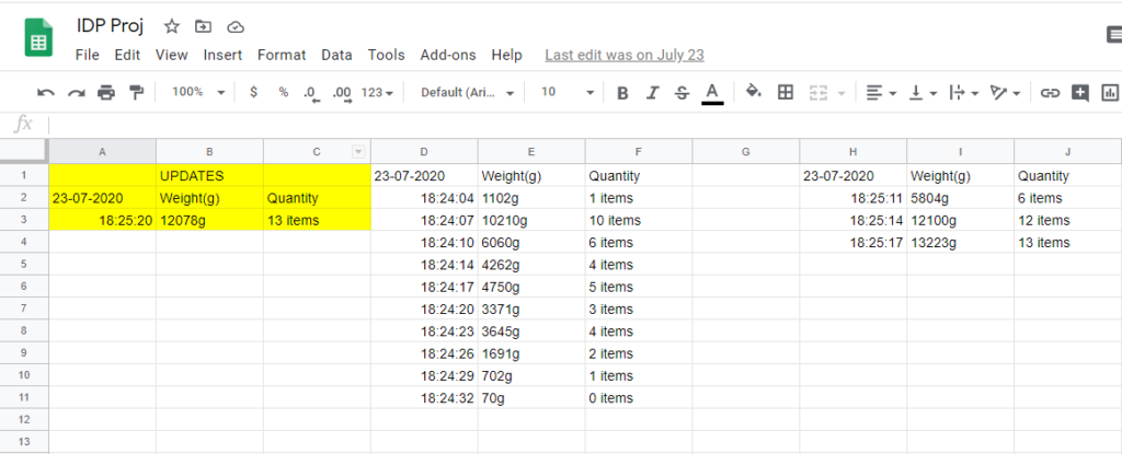
Once the parts are printed, and the weight sensors are attached on the four corners of the shelf, it was time to connect them up and start coding. The weight sensors are connected up to a HX711 Analog-to-Digital converter and the output of the HX711 is wired up to a Raspberry pi 4. After the testing was done, I started on the code. I programmed the raspberry pi to read the weight data from the shelf, divide that by the weight of one item on the shelf to get an approximate number of items on the shelf. I then programmed it to write the data to a Google Sheet page whenever there was a change in item quantity. I also connected an Oled screen to the raspberry pi to show the number of items on the shelf. The cons of using a weight sensor then became apparent – you can only measure one type of item with similar weights. However, this was not much of a problem as these weight sensors are rated to a high load and can be used in a manufacturing and shipping environment in which the products weight similarly in bulk.

Raspberry pi wired to the weight sensor with a HX711 ADC

The results we obtained was quite satisfactory. The weight sensors, although it may handle a high load (up to 200kg per sensor), does not lose its accuracy when measuring lighter loads. We were able to measure the weight changes up to ±5g accurately and update the google sheet in real time. One of my groupmate also developed an app to track the stock movements.

Here’s a short video of our initial system testing using the weight sensor:

Short demo of the weight sensor

RFID System

Next, I had to program for the RFID system of our project. The RFID reader was generously borrowed to us by another company specializing in RFID and IoT development. The RFID reader that they borrowed us did not come with a programmer’s manual and only had a ‘demo’ program. Hence, I had to think of a way to read the data off of the demo program and into my program.

I ended up using a python library called the PyTesseract, which is an optical character recognition library that can help me extract the valuable data from the demo program. I coded my program to take a screenshot of this demo program when it’s running, crop/resize it, and applied some filters to allow for the library to accurately recognize the unique ID (UID) of each RFID tags. The recognized UID can then be compared to a database to find out what product that UID is from. Once that was fully working, I had to program it to look for changes in the stock movement so that it may log it in Google Sheet which can be accessed through the same app that my groupmate created.

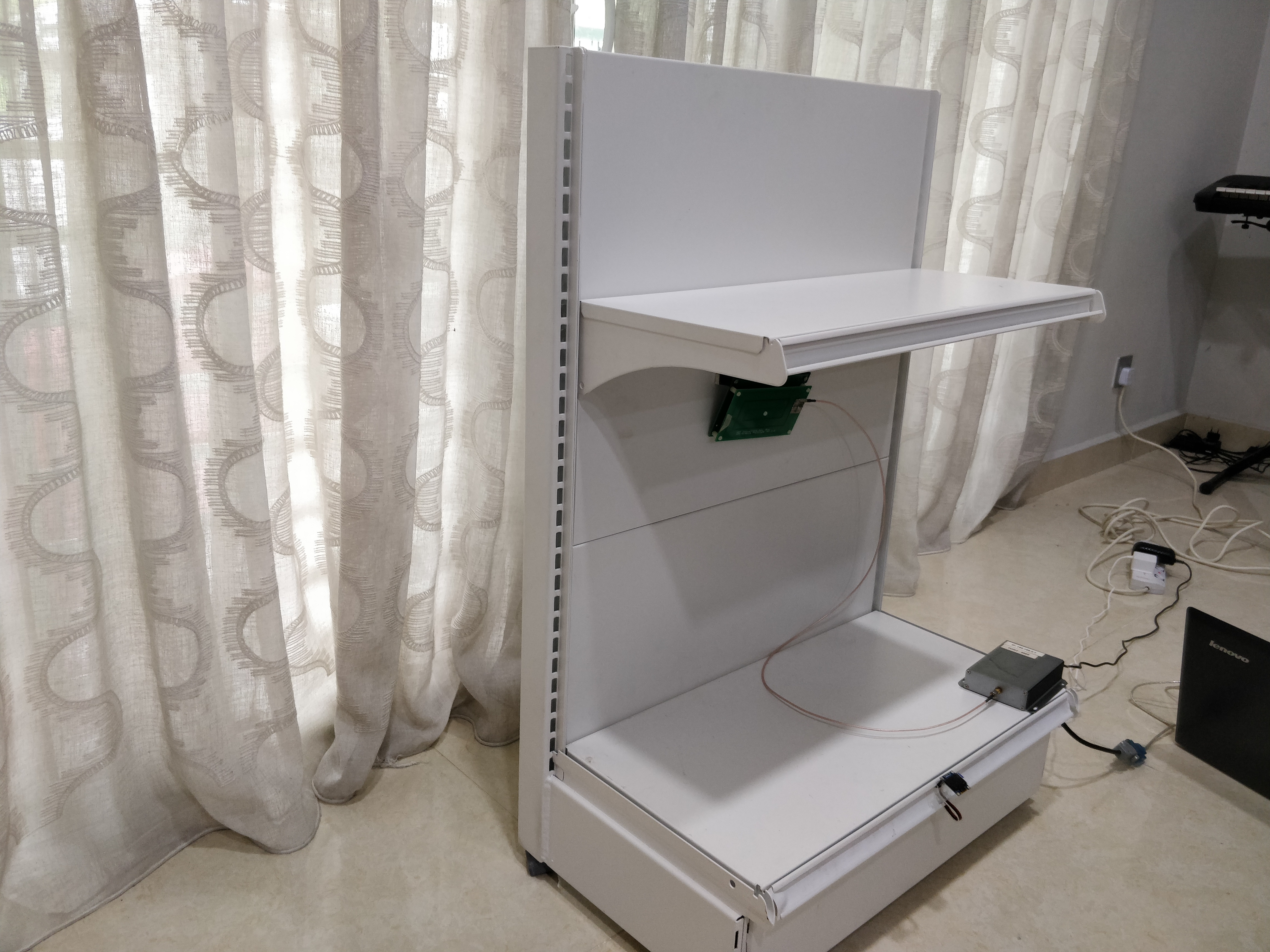
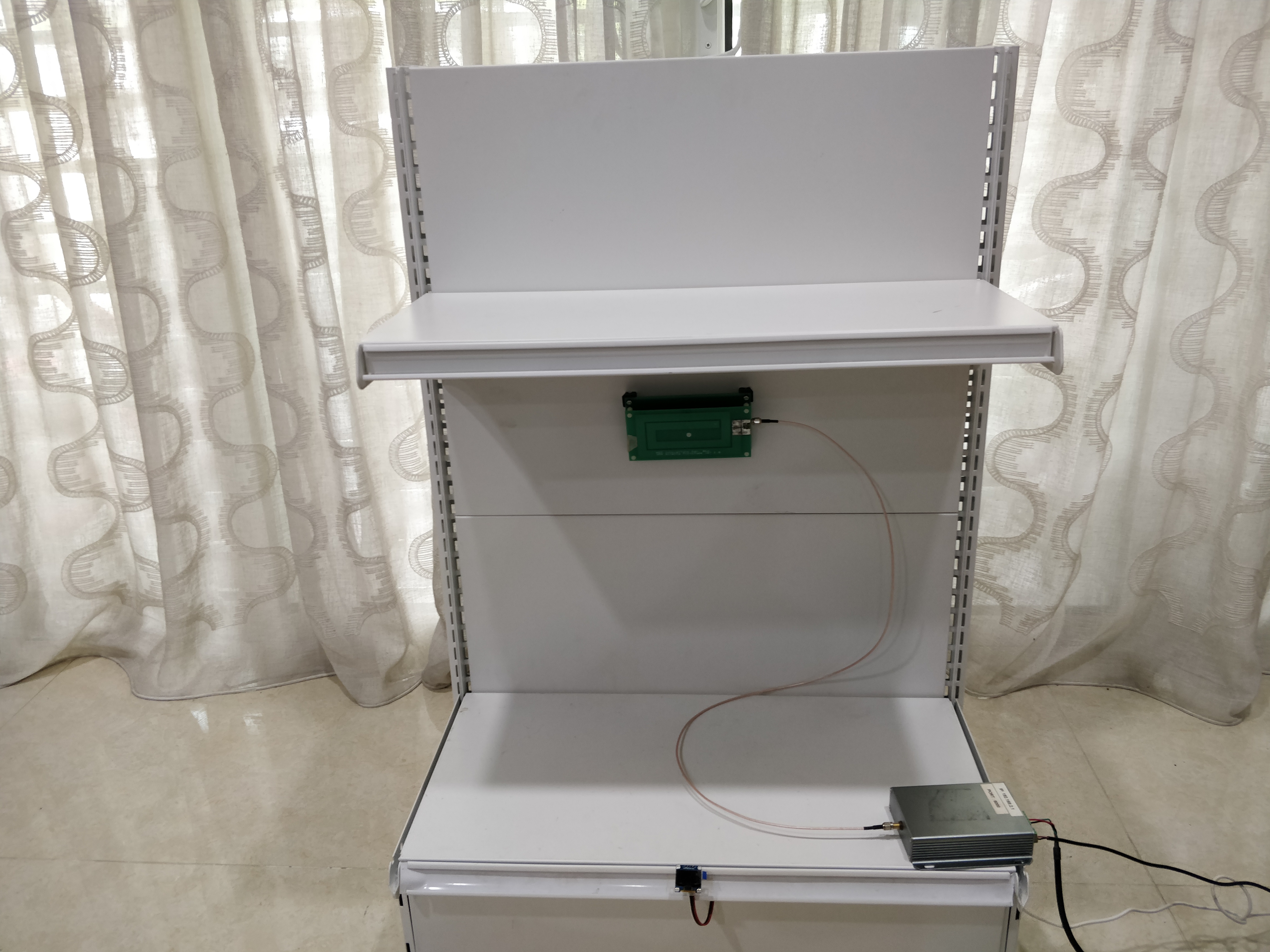
To attach the RFID antenna on the shelf itself, I had to design another part in Fusion 360. This part was made at an angle to ensure that the antenna has a maximum area of coverage with the tags. A magnet is embedded in the part to allow for the antenna to stick on the metallic wall of the shelf.

PCB design

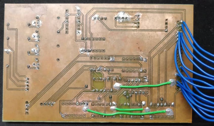
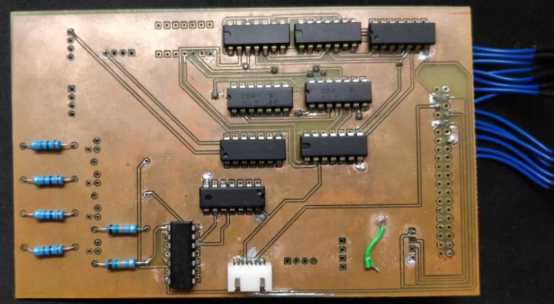
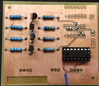
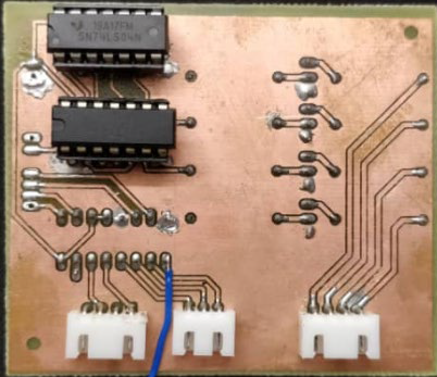
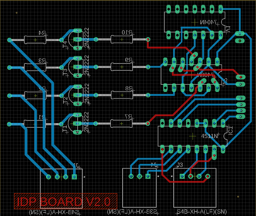
Once we got everything working as intended, we wanted to take it a step further and develop our own PCB to reduce all the wirings. So we designed our board in Autodesk Eagle and produced the PCB in the University’s PCB fabrication lab.

Unfortunately, after very thorough and time consuming testing and debugging, we couldn’t get the PCB to work. We suspect there might be stray capacitances and inductances within the traces which cause erroneous readings on the output. We finally opted to go back to the breadboard version due to the lack of time.

Here’s a demo video of our completed Weight sensor and RFID sensor system:

Additional Features

After the main hardware and software components of the shelf is done, it was time to add some additional features to make the shelf ‘smart’. Initially, we planned to implement a neural network to predict the sales data of future sales given the current sale. However, due to the lack of time and insufficient datasets, we opted for a pseudo-AI system instead. We were able to achieve four additional features with our prototype which includes:-

  • An android application
  • Weather sales prediction
  • Holiday sales prediction
  • Google Trends prediction

Android Application

We’ve developed an app which allows a user to see the current product stock on the shelf which is meant for customers. We thought that at the current rampant stage of the covid-19 pandemic (at the time of this post), customers would more likely buy from a store in which they can check has their products in stock. This can also promote social distancing between the customers as they can check whether their items are in stock before going out to the store.

Holiday and Weather Sales Prediction

I’ve also coded a local holiday and a weather forecaster in our program, which is able to forecast the weather for the entire day as well as the local holiday for the next entire year. The program is able to make a pseudo-prediction on what the store should stock up on. These predictions will be updated every time the program is launched. In the future, if given enough time and sales data, there is a potential for true AI prediction that could be done based on previous holiday sales and weather data.

Google Keyword Analysis

I’ve also added a Google keyword trendline which is based on Google keyword searches in an area. It compares the frequency of searches of different keywords and plots the frequency in a frequency-time graph. For example:

With the graph obtained above which shows the frequency of searches of laptop models; if you were a computer salesperson and wanted to set up shop in Malaysia, it is clear that Asus is the more searched laptop brand in Malaysia and it’s more likely that the sales of Asus will be higher than the other laptops. The program will update this graph each time it’s launched with real-time data.

Conclusion

After close to 7 months, we finally have a finished a working prototype. This project was chosen as one of the finalists in our university’s Best Capstone Project awards. The code of this project can be found in my Github page. This code will not work straight out-of-the-box as I’ve removed some personal API keys and files from the project but this project can be used as a reference for anyone interested in doing something similar. Thanks for reading!
DC Variable Power Supply

Throughout the years in my engineering degree, one thing have always bugged me; the thought of always having to go to the University’s lab just to power my projects. This led me to the thought of buying a commercially available power supply. However, when researching for an affordable DC supply, I realized that the cost of a high quality single channel DC supply is a little too high for a university student to bear. So I did what engineers would do; I took it upon myself to design and build one myself.

Like the saying goes – Don’t reinvent the wheel, just realign it; I firstly went through the internet to search for what has already been done. I found lots of results mostly using a desktop power supply to supply fixed DC voltages. This was not what I wanted because the voltages of that supply can’t be adjusted and there was no protection schemes as well as current limiting in place in a typical computer power supply.

Furthering the search, I led myself into the world of lithium battery chargers and found out that a simple lithium battery charger has the required protection circuits and voltage variability that I was looking for. After a thorough search, I finally landed on a LTC3780 charging module which was typically used for charging Li-ion or Li-polymer batteries. This module was what I was looking for as it can provide a switching 1V-30V DC voltage as well as a load current of up to 10 A (although I probably will never have a use of that high load current, but better safe than sorry). Furthermore, with this module being a battery charging circuit, it has to come with multiple safety features. This means that this circuit itself provides most of the safety features that a standard lab power supply comes with, such as overcurrent protection, short circuit protection, and undervoltage protection. Lastly, this module costs much lesser than a full blown variable supply!

LTC3780 Module

Now that I’ve sourced the variable supply of the project, I need to purchase a few more components to fully complete this project. The components include:-

  • A 12V 5A power supply to power the LTC module
  • A 200kΩ and 500kΩ potentiometer to adjust the voltage and current limits.
  • Potentiometer knobs
  • AC input
  • AC Switch
  • Voltage/Current Display
  • Banana Plugs
  • 12VDC fan and fanguard
  • 7805 Voltage Regulator
  • Two rail toggle switch

All of these components are sourced from China, which comes with cheap parts albeit with a long shipping time.

While waiting for the parts, I started on designing my circuit. I wanted two output ports on my supply – a variable DC voltage supply, and a fixed 5V rail to power small electronics. Hence, I integrated a common 7805 voltage regulator within my circuit. I drew a rough sketch of how the overall wiring is supposed to look like. The diagram was drawn as a reference and wasn’t followed 100% (e.g. The fan I sourced was 12V instead of 8V and hence the voltage divider wasn’t needed).

Ink Drawings
Ink Drawings
Ink Drawings
Ink Drawings
Ink Drawings
Ink Drawings
Ink Drawings
Ink Drawings
Ink Drawings
Ink Drawings
Ink Drawings
Ink Drawings
Ink Drawings
Ink Drawings
Ink Drawings
Ink Drawings
Ink Drawings
Ink Drawings
Ink Drawings
Ink Drawings
Ink Drawings
Ink Drawings
Ink Drawings
Ink Drawings
Ink Drawings
Ink Drawings
Ink Drawings
Ink Drawings


Ink Drawings
Ink Drawings
Ink Drawings
Ink Drawings
Ink Drawings
Ink Drawings
Ink Drawings
Ink Drawings
Ink Drawings
Ink Drawings
Ink Drawings
Ink Drawings
Ink Drawings
Ink Drawings
Ink Drawings
Ink Drawings
Ink Drawings
Ink Drawings
Ink Drawings
Ink Drawings
Ink Drawings
Ink Drawings
Ink Drawings
Ink Drawings
Ink Drawings
Ink Drawings
Ink Drawings
Ink Drawings
Ink Drawings
Ink Drawings
Ink Drawings
Ink Drawings
Ink Drawings
Ink Drawings
Ink Drawings
Ink Drawings
Ink Drawings
Ink Drawings
Ink Drawings
Ink Drawings
Ink Drawings
Ink Drawings
Ink Drawings
Ink Drawings
Ink Drawings
Ink Drawings
Ink Drawings
Ink Drawings
Ink Drawings
Ink Drawings
Ink Drawings
Ink Drawings
Ink Drawings
Ink Drawings
Ink Drawings
Ink Drawings
Ink Drawings
Ink Drawings
Ink Drawings
Ink Drawings
Ink Drawings
Ink Drawings
Ink Drawings
Ink Drawings
Ink Drawings
Ink Drawings
Ink Drawings
Ink Drawings
Ink Drawings
Ink Drawings
Ink Drawings
Ink Drawings
Ink Drawings
Ink Drawings
Ink Drawings
Ink Drawings

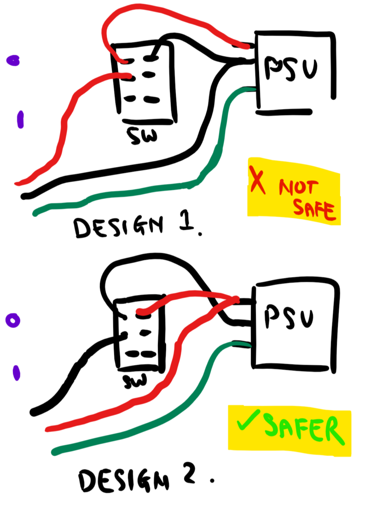
Not only that, I also did a quick design on how I should wire up the main 240V switch, as it was my first time wiring up a 6-pin ON/OFF switch with indicator lights.

With the wirings done, I drew a quick sketch on how I would assemble all the components in an enclosure.

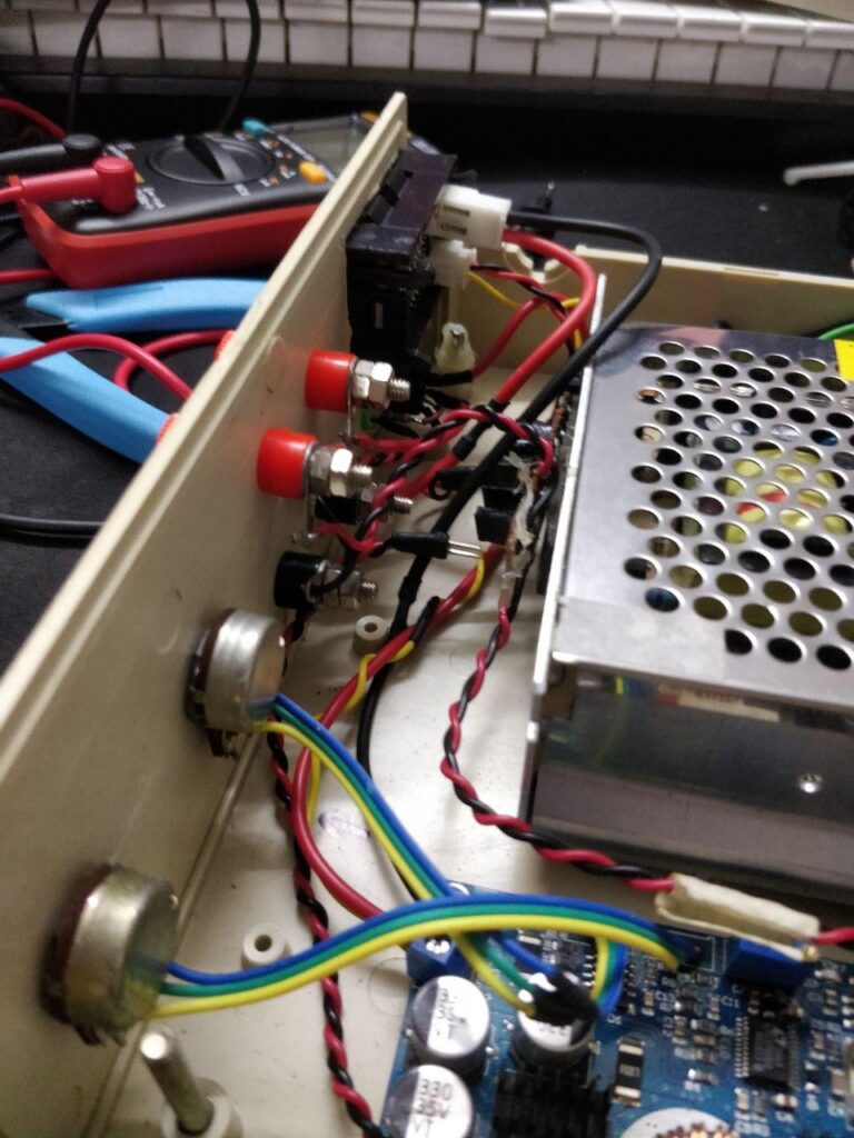
Finally, with the sketches drawn and the components arriving, I started the build by drilling holes and mounting each component and I’ve managed to fit the components in the enclosure!

Overall, it took about two days to wire everything and to test the fit of each component but I’m really proud of the results. Now I can have a cheap and adjustable power supply! (Please excuse the vertical video, I was filming with one hand and it was hard to hold the camera horizontally!)