
Introduction
Recently I’ve been trying to get myself into PCB fabrication using surface mount components to reduce the size of my prototype. Since I do not own a hot air rework station, it has been very difficult for me to solder surface mount components (SMD) by using a handheld soldering iron. Not only that, removing surface mount components are almost impossible using a handheld soldering iron because there are multiple points that has to be heated at the same time to remove the component. Therefore, I wanted to build myself a simple DIY SMD soldering station.
Methods and Results
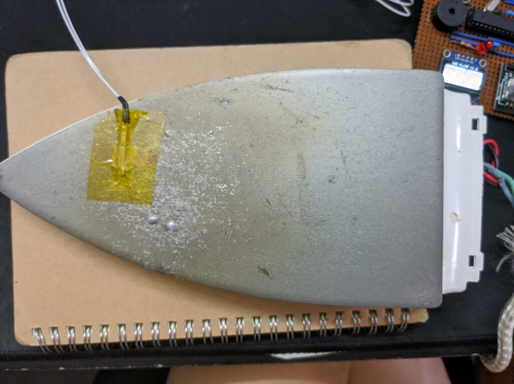
As always, I started by researching on the different methods of soldering SMD parts. I came across this guide that tried out most of the methods of SMD soldering. From that article, the hot-plate reflowing was one of the cheaper and more effective methods. However, instead of using a skillet (like from the article), I had an old flat clothes iron laying around which I thought could be a great upcycling opportunity. Time to start the disassembly process!
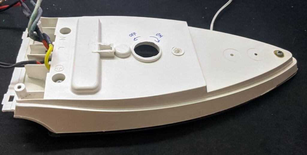
Clothes iron disassembled and unwanted parts cut off to make the back flat
The disassembly of the iron was quite straightforward. I had to remove a thermal fuse from the iron as the reflowing temperature will exceed the fuse’s rated temperature. The rest of the circuit was kept as intact as possible.
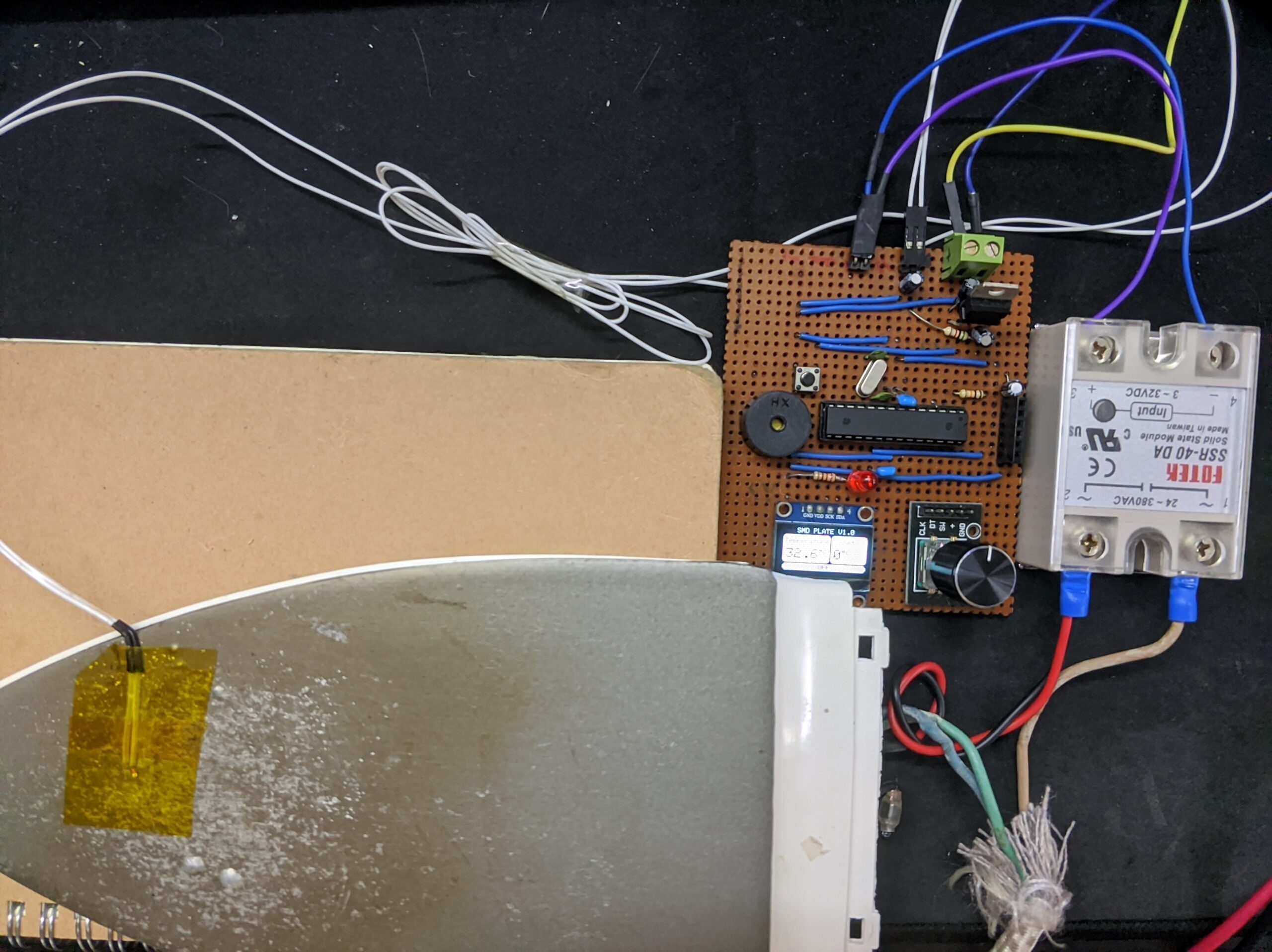
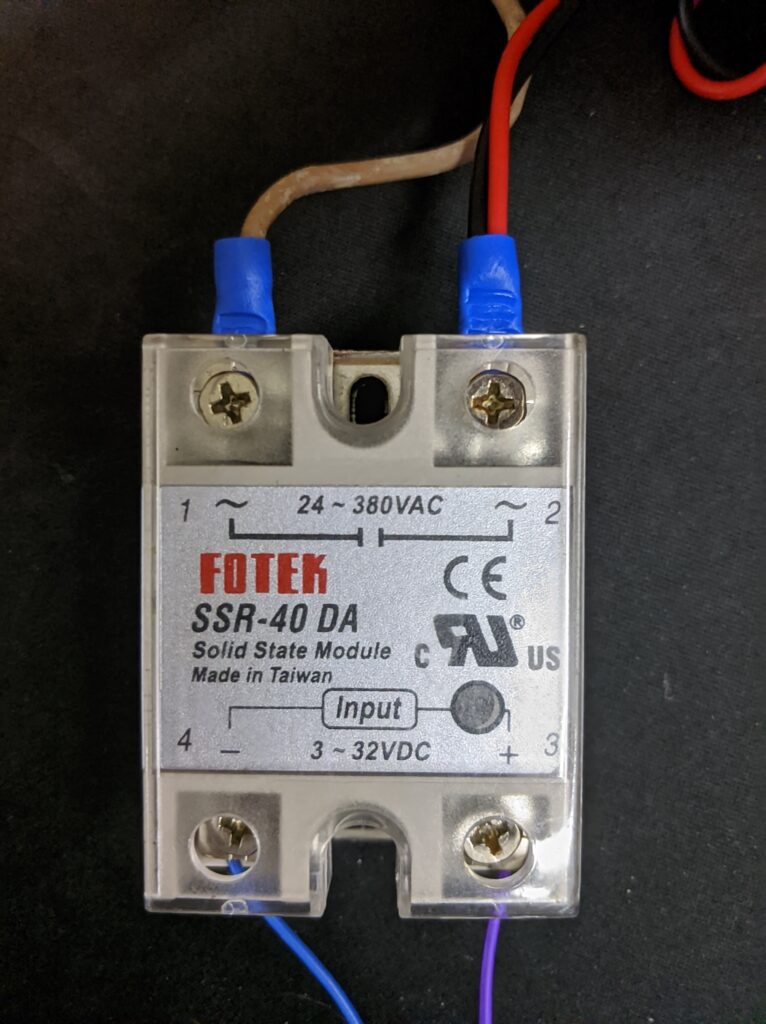
My plan was to add a simple temperature-controlled system to the iron by using a relay to switch the iron on and off and a temperature sensor as a feedback to the microcontroller. So I started a breadboard prototype using an Arduino Uno, a thermistor, and a solid-state relay.
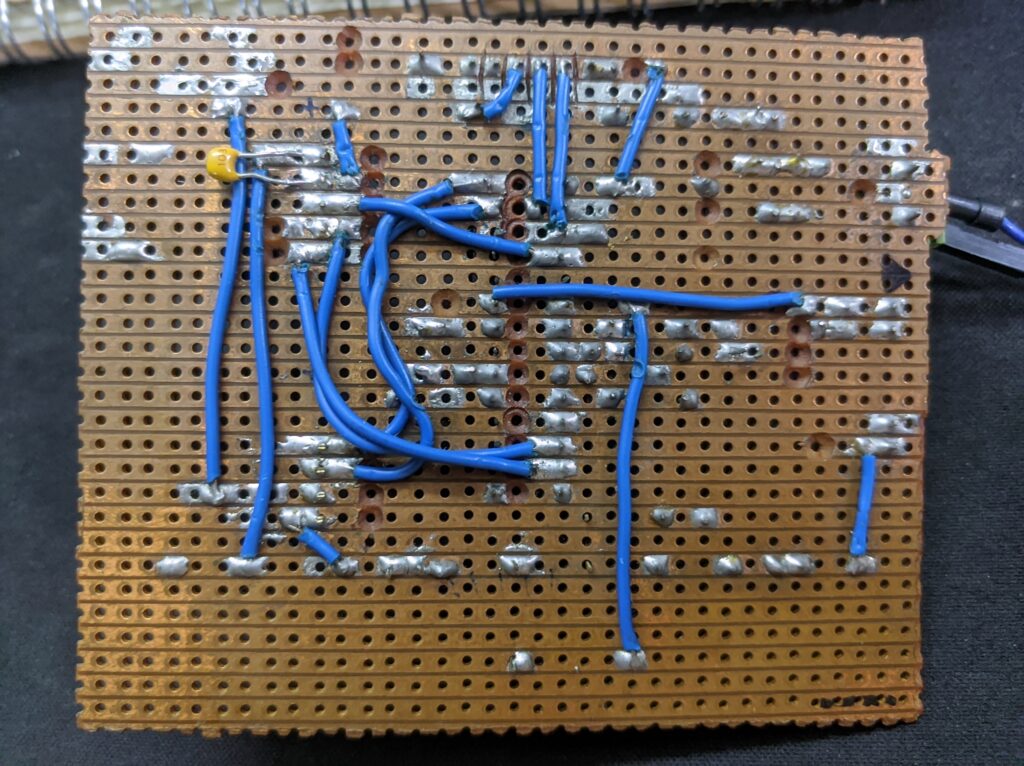
Once I have the basic functionality programmed and tested, I designed and hand-soldered a pcb with the ATMEGA328P as the microcontroller.
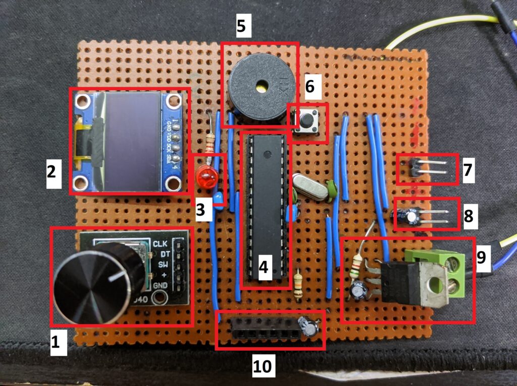
The components labelled in the picture above are as follows:
- Rotary Encoder
- 0.96″ OLED Display
- Relay Trigger Indicator
- ATMEGA328P Microcontroller
- Buzzer
- Reset Button
- Relay Header
- Thermistor Header
- 5V Regulator
- FTDI Header
The PCB is designed with a program reset button and an FTDI header to upload newer versions of the program. The temperature can be set by clicking the rotary encoder and rotating the knob. The red LED is an indicator light to show when the heater element is turned on. Double clicking the rotary encoder will allow for a preset temperature (set in the program) and a long press of the encoder will fully turn off the relay. After some iterations of the program, this is what I’ve ended up with:
By combining a relay and thermistor to the PCB and some addition of the code, I now have a working SMD reflow plate!

Once all of that was done, it was time to test solder an SMD LED and a 4020 package resistor. I initially set the plate to around 180°C as recommended by the manufacturer of the soldering paste. However, through multiple tests, I found out that that temperature is too low and it takes a very long time to turn the solder into a shiny blob of metal. This may be because the plate has to heat the bottom of the PCB and the heat has to transfer to the top of the PCB before melting the solder. In addition, PCB’s are not completely flat which means there is an air gap between the hot plate and the PCB. This causes the air to act as an insulation layer thus increasing the time needed to fully melt the solder.
Through several testing, I found that the optimal temperature for this hot plate is around 220-230°C. The full soldering process takes around 5 minutes (excluding adding the paste). I’m quite proud of how this turned out!
How It Works
The working principle of this system is actually pretty straightforward: the user will give a set temperature for the hot plate to achieve, the program will compare the current temperature with the set temperature. If the set temperature is higher than the current temperature, the relay turns on and vice versa. Although this is not the most accurate way of controlling the temperature (there will be oscillations caused by the thermal inertia of the iron), a threshold based system is the simplest way to achieve temperature control.
As the iron had a 1000W rating, the iron heated up too quickly and the thermal inertia of the iron caused the thermistor to react too slowly. This caused the iron to reach up to 270C with a set-point of 180C even after the relay switched off the iron. To prevent this, I had to limit the power consumption of the iron by implementing PWM switching. I had to lower the duty cycle to allow for only 20% of the max power to ensure that the iron does not heat up too quickly. A PID loop could be implemented to fix the aforementioned problem but limiting the power seemed to solve the issue so I didn’t bother to add a PID element. From there, it was a case of getting the Oled display, buzzer and a rotary encoder to act as an interface for the entire system.
A lot of time was spent debugging the PCB as the microcontroller and rotary encoder didn’t work correctly. I later found out this was caused by an unstable input voltage due to a noisy input voltage bus. However, that issue was fixed by adding decoupling capacitors close each of the input voltage on the microcontroller and the rotary encoder.
Conclusion
Overall, this project took me close to two months of on-and-off coding and debugging to complete. I’m really happy with how it turned out, and the next step is to add a base to attach all the components to. As always, the code to this project is completely open source and can be accessed from my Github project page. Thanks for reading!