

Throughout the years in my engineering degree, one thing have always bugged me; the thought of always having to go to the University’s lab just to power my projects. This led me to the thought of buying a commercially available power supply. However, when researching for an affordable DC supply, I realized that the cost of a high quality single channel DC supply is a little too high for a university student to bear. So I did what engineers would do; I took it upon myself to design and build one myself.
Like the saying goes – Don’t reinventing the wheel, just realign it; I firstly went through the internet to search for what has already been done. I found lots of results mostly using a desktop power supply to supply fixed DC voltages. This was not what I wanted because the voltages of that supply can’t be adjusted and there was no protection schemes as well as current limiting in place in a typical computer power supply.
Furthering the search, I led myself into the world of lithium battery chargers and found out that a simple lithium battery charger has the required protection circuits and voltage variability that I was looking for. After a thorough search, I finally landed on a LTC3780 charging module which was typically used for charging Li-ion or Li-polymer batteries. This module was what I was looking for as it can provide a switching 1V-30V DC voltage as well as a load current of up to 10 A (although I probably will never have a use of that high load current, but better safe than sorry). Furthermore, with this module being a battery charging circuit, it has to come with multiple safety features. This means that this circuit itself provides most of the safety features that a standard lab power supply comes with, such as overcurrent protection, short circuit protection, and undervoltage protection. Lastly, this module costs much lesser than a full blown variable supply!

Now that I’ve sourced the variable supply of the project, I need to purchase a few more components to fully complete this project. The components include:-
- A 12V 5A power supply to power the LTC module
- A 200kΩ and 500kΩ potentiometer to adjust the voltage and current limits.
- Potentiometer knobs
- AC input
- AC Switch
- Voltage/Current Display
- Banana Plugs
- 12VDC fan and fanguard
- 7805 Voltage Regulator
- Two rail toggle switch
All of these components are sourced from China, which comes with cheap parts albeit with a long shipping time.
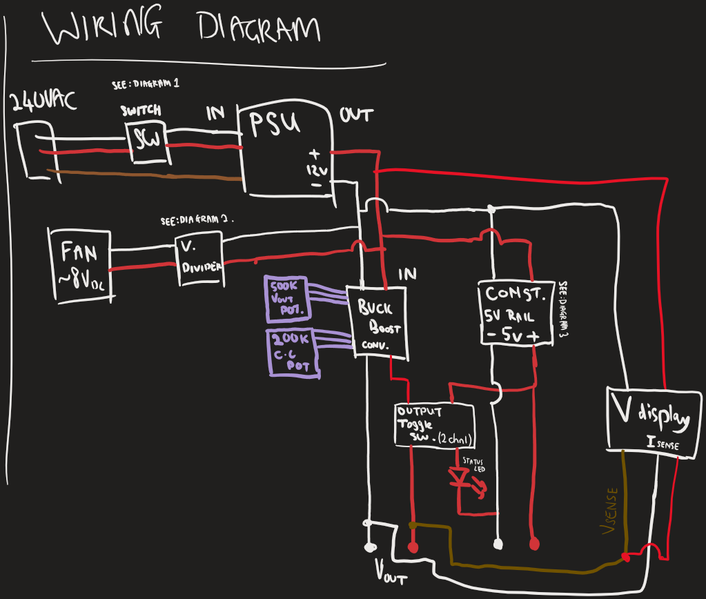
While waiting for the parts, I started on designing my circuit. I wanted two output ports on my supply – a variable DC voltage supply, and a fixed 5V rail to power small electronics. Hence, I integrated a common 7805 voltage regulator within my circuit. I drew a rough sketch of how the overall wiring is supposed to look like. The diagram was drawn as a reference and wasn’t followed 100% (e.g. The fan I sourced was 12V instead of 8V and hence the voltage divider wasn’t needed).
Not only that, I also did a quick design on how I should wire up the main 240V switch, as it was my first time wiring up a 6-pin ON/OFF switch with indicator lights.
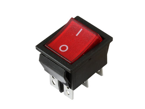
6-pin ON/OFF Switch 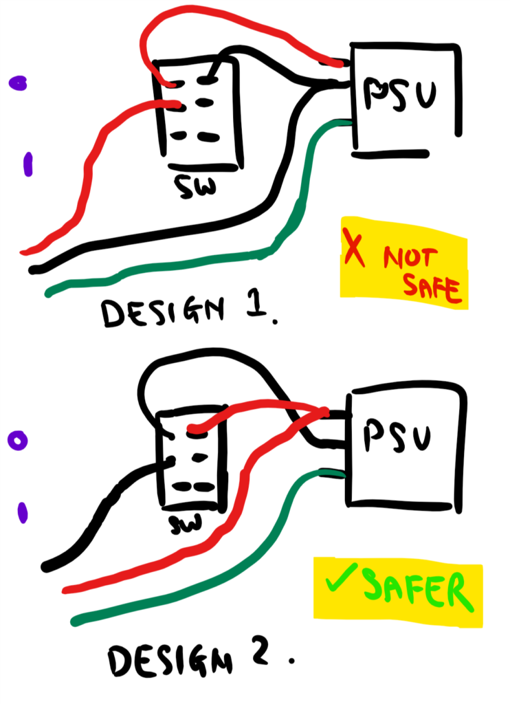
Wiring Diagram of switch
With the wirings done, I drew a quick sketch on how I would assemble all the components in an enclosure.


Finally, with the sketches drawn and the components arriving, I started the build by drilling holes and mounting each component and I’ve managed to fit the components in the enclosure!


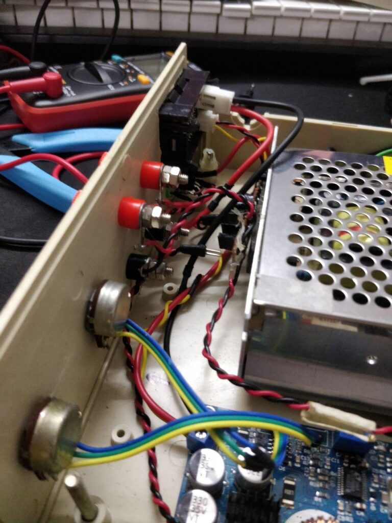

Overall, it took about two days to wire everything and to test the fit of each component but I’m really proud of the results. Now I can have a cheap and adjustable power supply! (Please excuse the vertical video, I was filming with one hand and it was hard to hold the camera horizontally!)