
Background
Building a scalable web application using AWS services, including Virtual Private Cloud (VPC), Elastic Compute Cloud (EC2), Relational Database Service (RDS), Elastic File System (EFS), Auto Scaling Group (ASG), and Application Load Balancer (ALB).
- Designed and implemented a highly available and fault-tolerant infrastructure that can handle a large number of concurrent users.
- Leveraged VPC to isolate the application and secure it with network access control lists and security groups.
- Used EC2 to deploy and manage the application servers, optimized for performance and cost.
- Set up RDS as the primary database for the application
- Utilized EFS for storing and sharing files across instances, with high throughput and low latency.
- Implemented ASG and ALB to dynamically scale and load balance the application, providing consistent and responsive user experience.
A 3-tier architecture is the most common implementation of a multi-tier architecture for hosting an application in the cloud. It provides a publicly accessible presentation tier, and two private logic and data tiers. The main benefits of running a 3-tier design is the improved horizontal scalability and availability which we will fully take advantage in this project. Furthermore, a 3-tier model abstracts the highly coupled dependency that a 1-tier architecture relies on (e.g. code changes done on a database system for a 1-tier architecture may break the presentation layer). This project will focus on building a 3-tier, fully elastic WordPress instance that scales according to load, and the resources will be managed via an Infrastructure as Code (IaC) tool, Terraform, to provide a fast and minimal error provisioning of resources.
Scope
The scope of this project mainly consists of abstracting each tier independent of one another, so that scaling can be done efficiently within each tier. Furthermore, to ensure a reliable and highly-available design, the services will span several availability zones across the region. In this case, we will use the us-east-1 region to provision our networking resources. The architecture design below shows the infrastructure that will be provisioned throughout this project. If you want to replicate this project in your environment, you can find the terraform code from my Github project page.
1. Networking
Firstly, before we start provisioning resources, we will need to determine which IP we can use for our VPC and subnets. In my case, since I do not have any prior network environment within AWS and this project will be torn down later, I have the freedom to choose my CIDR range. In a production environment, make sure that there are no overlapping ranges to all of your networks. Factors such as the VPC size, existing on-premises networking, 3rd party Cloud-reserved networking all contribute to the consideration when picking the most suitable VPC range.
In this case, I have decided to avoid a few IP ranges I know might collide with existing infrastructure:
192.168.0.0/16 –reserved for local networking
10.0.0.0/16 – reserved for default AWS cloud networking
172.31.0.0/16 – reserved for default Azure cloud networking (also same range as default VPC)
10.128.0.0/9 – reserved for default Google cloud networking
Taken the above ranges into consideration, we will then think about the number of networks that this WordPress instance will need. In this case, I have decided that the 3-tier architecture (+1 spare for future-proofing) should be resilient across 3 Availability Zones. This means we will need a total of 12 subnets. Picking a VPC CIDR range of 10.16.0.0/16, we can split the /16 into 12 subnets (total of 16, but we only use 12), and each of the subnets is a /20 subnet (4091 IPs).
For VPC range of 10.16.0.0/16:
| Subnets | AZ-A | AZ-B | AZ-C |
| SNDB (private) | 10.16.16.0/20 | 10.16.80.0/20 | 10.16.144.0/20 |
| SNAPP (private) | 10.16.32.0/20 | 10.16.96.0/20 | 10.16.160.0/20 |
| SNPUB (public) | 10.16.48.0/20 | 10.16.112.0/20 | 10.16.176.0/20 |
| SPARE | 10.16.64.0/20 | 10.16.128.0/20 | 10.16.192.0/20 |
Now that we have our subnet IP mapped out, we can start provisioning the networking infrastructure using terraform, as shown below:
resource "aws_vpc" "main" {
  cidr_block                       = "10.16.0.0/16"
  assign_generated_ipv6_cidr_block = true
  enable_dns_hostnames             = true
  enable_dns_support               = true
  tags = {
    Name = "WP-VPC"
  }
}
To determine the availability zone within our region, we can use a the aws_availability_zones data structure in terraform and filter by the available state.
data "aws_availability_zones" "availableAZ" {
  state = "available"
  filter {
    name   = "opt-in-status"
    values = ["opt-in-not-required"]
  }
}
And create the subnets with pre-defined IP based on the availability zones:
resource "aws_subnet" "SNDB-A" {
  vpc_id                          = aws_vpc.main.id
  cidr_block                      = "10.16.16.0/20"
  availability_zone               = data.aws_availability_zones.availableAZ.names[0]
  ipv6_cidr_block                 = cidrsubnet(aws_vpc.main.ipv6_cidr_block, 8, 1)
  assign_ipv6_address_on_creation = true
  tags = {
    Name = "SNDB-A"
  }
}
resource "aws_subnet" "SNDB-B" {
  vpc_id            = aws_vpc.main.id
  cidr_block        = "10.16.80.0/20"
  availability_zone = data.aws_availability_zones.availableAZ.names[1]
  ipv6_cidr_block   = cidrsubnet(aws_vpc.main.ipv6_cidr_block, 8, 5)

  assign_ipv6_address_on_creation = true

  tags = {
    Name = "SNDB-B"
  }
}
resource "aws_subnet" "SNDB-C" {
  vpc_id            = aws_vpc.main.id
  cidr_block        = "10.16.144.0/20"
  availability_zone = data.aws_availability_zones.availableAZ.names[2]
  ipv6_cidr_block   = cidrsubnet(aws_vpc.main.ipv6_cidr_block, 8, 9)

  assign_ipv6_address_on_creation = true

  tags = {
    Name = "SNDB-C"
  }
}

resource "aws_subnet" "SNAPP-A" {
  vpc_id            = aws_vpc.main.id
  cidr_block        = "10.16.32.0/20"
  availability_zone = data.aws_availability_zones.availableAZ.names[0]
  ipv6_cidr_block   = cidrsubnet(aws_vpc.main.ipv6_cidr_block, 8, 2)

  assign_ipv6_address_on_creation = true

  tags = {
    Name = "SNAPP-A"
  }
}
resource "aws_subnet" "SNAPP-B" {
  vpc_id            = aws_vpc.main.id
  cidr_block        = "10.16.96.0/20"
  availability_zone = data.aws_availability_zones.availableAZ.names[1]
  ipv6_cidr_block   = cidrsubnet(aws_vpc.main.ipv6_cidr_block, 8, 6)

  assign_ipv6_address_on_creation = true

  tags = {
    Name = "SNAPP-B"
  }
}
resource "aws_subnet" "SNAPP-C" {
  vpc_id            = aws_vpc.main.id
  cidr_block        = "10.16.160.0/20"
  availability_zone = data.aws_availability_zones.availableAZ.names[2]
  ipv6_cidr_block   = cidrsubnet(aws_vpc.main.ipv6_cidr_block, 8, 10)

  assign_ipv6_address_on_creation = true

  tags = {
    Name = "SNAPP-C"
  }
}

resource "aws_subnet" "SNPUB-A" {
  vpc_id            = aws_vpc.main.id
  cidr_block        = "10.16.48.0/20"
  availability_zone = data.aws_availability_zones.availableAZ.names[0]
  ipv6_cidr_block   = cidrsubnet(aws_vpc.main.ipv6_cidr_block, 8, 3)

  assign_ipv6_address_on_creation = true

  tags = {
    Name = "SNPUB-A"
  }
}
resource "aws_subnet" "SNPUB-B" {
  vpc_id            = aws_vpc.main.id
  cidr_block        = "10.16.112.0/20"
  availability_zone = data.aws_availability_zones.availableAZ.names[1]
  ipv6_cidr_block   = cidrsubnet(aws_vpc.main.ipv6_cidr_block, 8, 7)

  assign_ipv6_address_on_creation = true

  tags = {
    Name = "SNPUB-B"
  }
}
resource "aws_subnet" "SNPUB-C" {
  vpc_id            = aws_vpc.main.id
  cidr_block        = "10.16.176.0/20"
  availability_zone = data.aws_availability_zones.availableAZ.names[2]
  ipv6_cidr_block   = cidrsubnet(aws_vpc.main.ipv6_cidr_block, 8, 11)

  assign_ipv6_address_on_creation = true

  tags = {
    Name = "SNPUB-C"
  }
}
Next, for our public subnets SNPUB-X to be able to connect to the public internet, we will need to attach an internet gateway (IGW) to our VPC, and also define the Route Table for each of our public subnet to route all IPv4 and IPv6 IPs to the IGW.
resource "aws_internet_gateway" "WP-IGW" {
  vpc_id = aws_vpc.main.id

  tags = {
    Name = "WP-IGW"
  }
}
resource "aws_route_table" "PUB-SN-RT" {
vpc_id = aws_vpc.main.id
route {
cidr_block = "0.0.0.0/0"
gateway_id = aws_internet_gateway.WP-IGW.id
}
route {
ipv6_cidr_block = "::/0"
gateway_id = aws_internet_gateway.WP-IGW.id
}
tags = {
Name = "VPC-WP-RT-PUB"
}
}
resource "aws_route_table_association" "RT-PUB-SNA" {
subnet_id = aws_subnet.SNPUB-A.id
route_table_id = aws_route_table.PUB-SN-RT.id
}
resource "aws_route_table_association" "RT-PUB-SNB" {
subnet_id = aws_subnet.SNPUB-B.id
route_table_id = aws_route_table.PUB-SN-RT.id
}
resource "aws_route_table_association" "RT-PUB-SNC" {
subnet_id = aws_subnet.SNPUB-C.id
route_table_id = aws_route_table.PUB-SN-RT.id
}
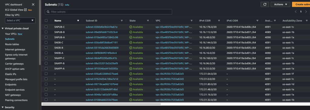
Applying the Terraform plan, we get the following subnets created:
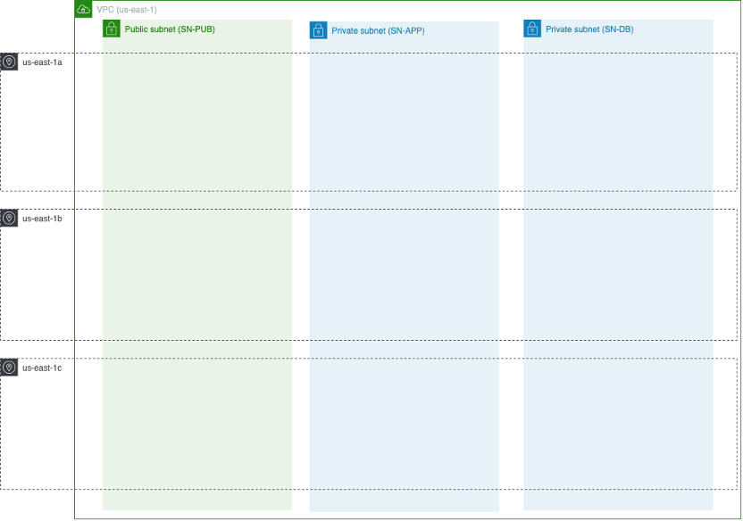
With that, the networking infrastructure is fully created. At this point, we have accomplished the following architecture in our design:
2. Database
Now that the networking is done, all of our resources can be provisioned with regards to these subnets. Firstly, we can implement a database system for the WordPress instance. WordPress uses a database to store and retrieve content such as the information of users, posts, comments and links in your website. By default, the database engine is installed and run locally within the EC2 instance. This will not be an issue if you only have one EC2 instance running the server; however, this does not work with an elastic EC2 architecture that scales in and out according to load as the data will be deleted every time the instance gets terminated.
To solve this issue, we can use Amazon’s Relational Database System (RDS). RDS is a fully managed Database-as-a-service (DBaaS) provider which supports an array of database engines including MySQL, which is used by WordPress. For this project, I will use the free-tier which does not provide multiple availability zone resiliency or read replicas. Of course, for production use cases, I would recommend to use multi-AZ read replicas to take advantage of the enhanced performance and increased availability that multi-AZ provides. We firstly have to define the subnets that the RDS instance will be provisioned in. In our case, it will be SNDB-A, SNDB-B, and SNDB-C. The free-tier will randomly pick one subnet and only provision one instance among these three subnets.
resource "aws_db_subnet_group" "WP-RDS-sn-group" {
  name_prefix = "wp-rds-sngroup-"
  description = "Wordpress RDS Subnet Group"
  subnet_ids  = [var.SNDB-A-ID, var.SNDB-B-ID, var.SNDB-C-ID]

  tags = {
    Name = "WP DB subnet group"
  }
}
resource "aws_db_instance" "wp-rds-db" {
  identifier_prefix          = "wp-rds-db-"
  db_name                    = var.SSM-DB-NAME
  engine                     = "mysql"
  engine_version             = "8.0"
  availability_zone          = "${var.current-region}a"
  auto_minor_version_upgrade = true
  instance_class             = "db.t3.micro"
  multi_az                   = false
  username                   = var.SSM-DB-USERNAME
  password                   = var.SSM-DB-PASSWORD
  db_subnet_group_name       = aws_db_subnet_group.WP-RDS-sn-group.name
  publicly_accessible        = false
  allocated_storage          = 200
  max_allocated_storage      = 1000
  vpc_security_group_ids     = [var.SG-DB-ID]
  skip_final_snapshot        = true
}
*PS: Make sure not to push your DB username and password to your repository!
Besides provisioning the RDS instance, we need to define the firewall that this database should inherit. Since WordPress runs on MySQL, port 3306 running on TCP should be opened as an ingress point.
resource "aws_security_group" "SG-DB" {
  name_prefix = "SG-DB-"
  description = "Control access to Database"
  vpc_id      = aws_vpc.main.id

  ingress {
    description     = "Allow MySQL IN"
    from_port       = 3306
    to_port         = 3306
    protocol        = "tcp"
    security_groups = [aws_security_group.SG-WP.id]
  }
  egress {
    from_port        = 0
    to_port          = 0
    protocol         = "-1"
    cidr_blocks      = ["0.0.0.0/0"]
    ipv6_cidr_blocks = ["::/0"]
  }

  tags = {
    Name = "SG-DB"
  }
}
Finally, to connect this DB to our EC2 instance, we will need to output the RDS endpoint and save it to AWS System’s manager as an SSM parameter so that we can input this value during EC2 provisioning.
#output DB endpoint to send to SSM-parameter
output "RDS-ENDPOINT" {
  value = aws_db_instance.wp-rds-db.address
}
resource "aws_ssm_parameter" "DBEndpoint" {
  name  = "/Wordpress/DBEndpoint"
  type  = "String"
  value = var.DB-ENDPOINT
}
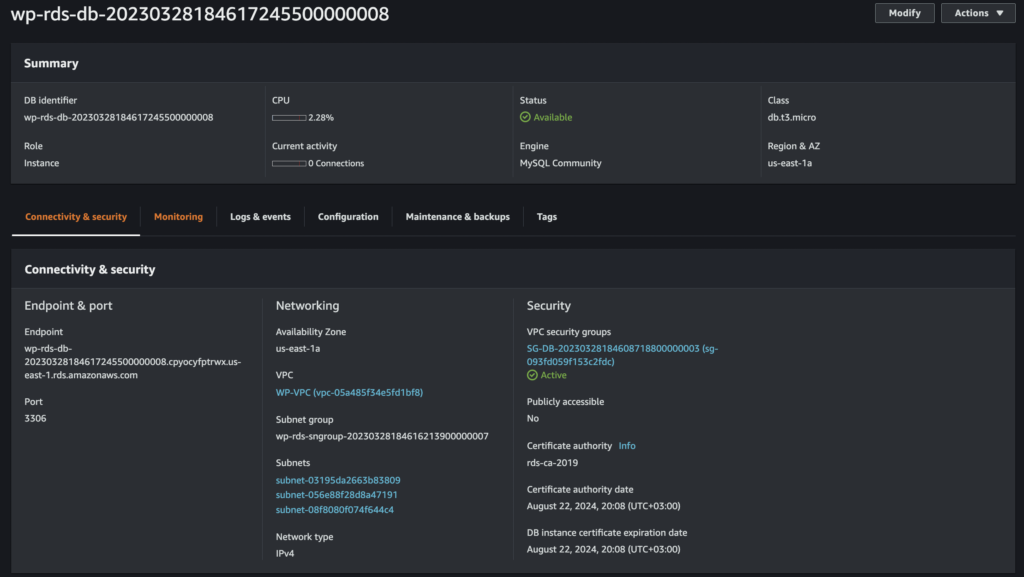
After applying the Terraform plan, we can see that a new RDS instance was created in the AWS console with the corresponding subnet and security groups attached.
3. Elastic File System
Now that we have a fully managed DB system that is able to store all of WordPress’ post metadata and user info, there is still one caveat; the DB engine is not designed to store large image/video files of our server and those files should also not be stored locally within the EC2 instance. Therefore, we require another way to store image and video files. This is where we can take advantage of Amazon’s Elastic File System (EFS). Amazon EFS is a managed file storage system that can provide persistent storage while being accessed by multiple instances concurrently.
The logic goes like this: we can configure an EC2 instance to mount an EFS storage to appear as network storage within the instance and store all files to this location. EFS will then store all these files on its own managed servers that is opaque to the user, thus decoupling the file-system from the EC2 instance.
To accomplish that, we can create an EFS instance and mount it to the three APP subnets. Similar to RDS, we will also need to provide a security group to allow the EC2 to connect to this instance.
resource "aws_security_group" "SG-EFS" {
  name_prefix = "SG-EFS-"
  description = "Control access to File System"
  vpc_id      = aws_vpc.main.id

  ingress {
    description     = "Allow NFS/EFS IPv4 IN"
    from_port       = 2049
    to_port         = 2049
    protocol        = "tcp"
    security_groups = [aws_security_group.SG-WP.id]
  }
  egress {
    from_port        = 0
    to_port          = 0
    protocol         = "-1"
    cidr_blocks      = ["0.0.0.0/0"]
    ipv6_cidr_blocks = ["::/0"]
  }

  tags = {
    Name = "SG-EFS"
  }
}
resource "aws_efs_file_system" "WP-EFS" {
  creation_token = "WP-CONTENT"

  lifecycle_policy {
    transition_to_ia = "AFTER_30_DAYS"
  }
  tags = {
    Name = "WP-Content-EFS"
  }
}
resource "aws_efs_backup_policy" "policy" {
  file_system_id = aws_efs_file_system.WP-EFS.id

  backup_policy {
    status = "ENABLED"
  }
}
resource "aws_efs_mount_target" "SNAPP-A-MOUNT-TARGET" {
  file_system_id  = aws_efs_file_system.WP-EFS.id
  subnet_id       = var.SNAPP-A-ID
  security_groups = [var.EFS-SG-ID]
}

resource "aws_efs_mount_target" "SNAPP-B-MOUNT-TARGET" {
  file_system_id  = aws_efs_file_system.WP-EFS.id
  subnet_id       = var.SNAPP-B-ID
  security_groups = [var.EFS-SG-ID]
}

resource "aws_efs_mount_target" "SNAPP-C-MOUNT-TARGET" {
  file_system_id  = aws_efs_file_system.WP-EFS.id
  subnet_id       = var.SNAPP-C-ID
  security_groups = [var.EFS-SG-ID]
}
Finally, to connect EFS to our EC2 instance, we will need to output the file system ID and save it to AWS System’s manager as an SSM parameter so that we can input this value during EC2 provisioning.
#output FS-ID to send to SSM-parameter
output "FS-ID" {
  value = aws_efs_file_system.WP-EFS.id
}
resource "aws_ssm_parameter" "EFS-ID" {
name = "/Wordpress/EFSFSID"
type = "String"
value = var.EFS-ID
}
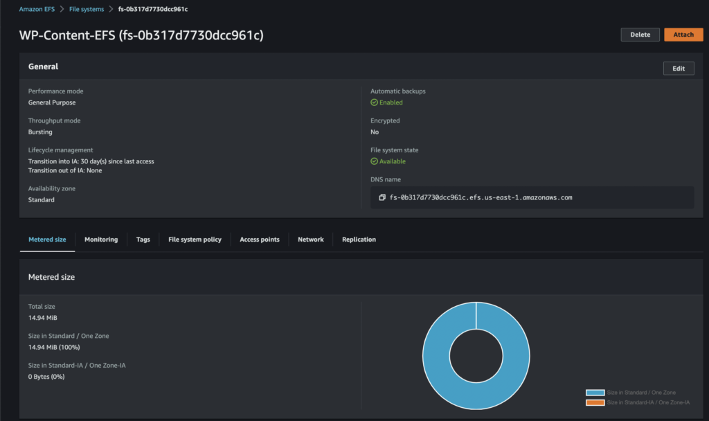
After applying the Terraform plan and checking the AWS console, we can see an EFS instance was created

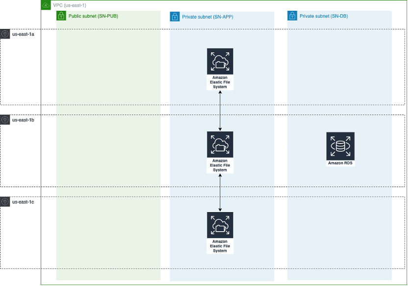
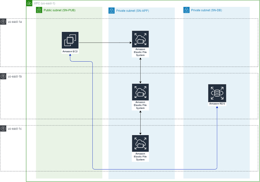
Now, after initialising both the RDS and EFS on the network, we now have an updated architectural diagram as so:
4. Elastic Compute Cloud
*This instance is for testing only, remember to remove it before moving on to the next module!
Now, we can test our EFS and RDS deployment by launching a test EC2 instance. I have decided to use a launch template to configure the EC2 instance as later we will be using the auto scaling group to launch our instances. Launching an instance with the launch template will only provision an EC2 instance within the SNPUB-A subnet. We will also require a security group for our WordPress instance.
Creating the security group:
resource "aws_security_group" "SG-WP" {
  name_prefix = "SG-WP-"
  description = "Control access to WordPress instances"
  vpc_id      = aws_vpc.main.id

  ingress {
    description = "Allow HTTP IPv4 IN"
    from_port   = 80
    to_port     = 80
    protocol    = "tcp"
    cidr_blocks = ["0.0.0.0/0"]
  }

  egress {
    from_port        = 0
    to_port          = 0
    protocol         = "-1"
    cidr_blocks      = ["0.0.0.0/0"]
    ipv6_cidr_blocks = ["::/0"]
  }

  tags = {
    Name = "SG-WP"
  }
}
Creating the launch template:
resource "aws_launch_template" "ec2-launch-template" {
  name                   = "WP-Launch-Template"
  description            = "Single server DP and App"
  image_id               = data.aws_ami.Amazon-Linux.id
  instance_type          = "t2.micro"
  user_data              = filebase64("${path.module}/WP-initialize.sh")
  update_default_version = true

  iam_instance_profile {
    name = var.instance-profile
  }

  network_interfaces {
    associate_public_ip_address = true
    delete_on_termination       = true
    security_groups             = [var.WP-security-group-id]
  }

  credit_specification {
    cpu_credits = "standard"
  }
}

data "aws_ami" "Amazon-Linux" {
  owners      = ["amazon"]
  most_recent = true
  filter {
    name   = "virtualization-type"
    values = ["hvm"]
  }
  filter {
    name   = "architecture"
    values = ["x86_64"]
  }
  filter {
    name   = "name"
    values = ["amzn2-ami-kernel-5.10-hvm-2.0*"]
  }
}
Creating the test EC2 instance (remove before moving to next step):
resource "aws_instance" "WP-instance" {
  subnet_id = var.SNPUB-A-ID
  launch_template {
    id = aws_launch_template.ec2-launch-template.id
  }
  tags = {
    Name = "WP-ec2-instance"
  }
  depends_on = [var.RDS-endpoint-address, var.EFS-ID, aws_lb.WP-ALB]
}
For the instances, we will need to provide an IAM role with several permissions to access several services so that the instance can access the required data: –
- CloudWatch agent: required to monitor detailed system-level EC2 metrics
- Amazon SSM: required to access SSM Parameters needed to import our RDS and EFS endpoints to connect to those services.
- Amazon EFS access: required to access and read files within the file system.
We can provide these permissions via Terraform like so:
#Policy document specifying what service can assume the role
data "aws_iam_policy_document" "WP-Role" {
  statement {
    effect  = "Allow"
    actions = ["sts:AssumeRole"]
    principals {
      type        = "Service"
      identifiers = ["ec2.amazonaws.com"]
    }
  }
}

resource "aws_iam_role" "WP-Role" {
  name                = "WP-Role"
  assume_role_policy  = data.aws_iam_policy_document.WP-Role.json
  managed_policy_arns = ["arn:aws:iam::aws:policy/CloudWatchAgentServerPolicy", "arn:aws:iam::aws:policy/AmazonSSMFullAccess", "arn:aws:iam::aws:policy/AmazonElasticFileSystemClientFullAccess"]
}

resource "aws_iam_instance_profile" "WP-Instance-Profile" {
  name = "WP_Instance_Profile"
  role = aws_iam_role.WP-Role.name
}
The launch template uses the bash script below to initialise the EC2 instance. The bash script imports the values from SSM parameter and modifies the EC2 instance to connect to the our RDS and EFS instances.
#!/bin/bash -xe
ALBDNSNAME=$(aws ssm get-parameters --region us-east-1 --names /Wordpress/ALBDNSNAME --query Parameters[0].Value)
ALBDNSNAME=`echo $ALBDNSNAME | sed -e 's/^"//' -e 's/"$//'`
EFSFSID=$(aws ssm get-parameters --region us-east-1 --names /Wordpress/EFSFSID --query Parameters[0].Value)
EFSFSID=`echo $EFSFSID | sed -e 's/^"//' -e 's/"$//'`
DBPassword=$(aws ssm get-parameters --region us-east-1 --names /Wordpress/DBPassword --with-decryption --query Parameters[0].Value)
DBPassword=`echo $DBPassword | sed -e 's/^"//' -e 's/"$//'`
DBRootPassword=$(aws ssm get-parameters --region us-east-1 --names /Wordpress/DBRootPassword --with-decryption --query Parameters[0].Value)
DBRootPassword=`echo $DBRootPassword | sed -e 's/^"//' -e 's/"$//'`
DBUser=$(aws ssm get-parameters --region us-east-1 --names /Wordpress/DBUser --query Parameters[0].Value)
DBUser=`echo $DBUser | sed -e 's/^"//' -e 's/"$//'`
DBName=$(aws ssm get-parameters --region us-east-1 --names /Wordpress/DBName --query Parameters[0].Value)
DBName=`echo $DBName | sed -e 's/^"//' -e 's/"$//'`
DBEndpoint=$(aws ssm get-parameters --region us-east-1 --names /Wordpress/DBEndpoint --query Parameters[0].Value)
DBEndpoint=`echo $DBEndpoint | sed -e 's/^"//' -e 's/"$//'`
yum -y update
yum -y upgrade
yum install -y mariadb-server httpd wget amazon-efs-utils
amazon-linux-extras install -y lamp-mariadb10.2-php7.2 php7.2
amazon-linux-extras install epel -y
yum install stress -y
systemctl enable httpd
systemctl start httpd
mkdir -p /var/www/html/wp-content
chown -R ec2-user:apache /var/www/
echo -e "$EFSFSID:/ /var/www/html/wp-content efs _netdev,tls,iam 0 0" >> /etc/fstab
mount -a -t efs defaults
wget http://wordpress.org/latest.tar.gz -P /var/www/html
cd /var/www/html
tar -zxvf latest.tar.gz
cp -rvf wordpress/* .
rm -R wordpress
rm latest.tar.gz
sudo cp ./wp-config-sample.php ./wp-config.php
sed -i "s/'database_name_here'/'$DBName'/g" wp-config.php
sed -i "s/'username_here'/'$DBUser'/g" wp-config.php
sed -i "s/'password_here'/'$DBPassword'/g" wp-config.php
sed -i "s/'localhost'/'$DBEndpoint'/g" wp-config.php
usermod -a -G apache ec2-user
chown -R ec2-user:apache /var/www
chmod 2775 /var/www
find /var/www -type d -exec chmod 2775 {} \;
find /var/www -type f -exec chmod 0664 {} \;
cat >> /home/ec2-user/update_wp_ip.sh<< 'EOF'
#!/bin/bash
source <(php -r 'require("/var/www/html/wp-config.php"); echo("DB_NAME=".DB_NAME."; DB_USER=".DB_USER."; DB_PASSWORD=".DB_PASSWORD."; DB_HOST=".DB_HOST); ')
SQL_COMMAND="mysql -u $DB_USER -h $DB_HOST -p$DB_PASSWORD $DB_NAME -e"
OLD_URL=$(mysql -u $DB_USER -h $DB_HOST -p$DB_PASSWORD $DB_NAME -e 'select option_value from wp_options where option_id = 1;' | grep http)
ALBDNSNAME=$(aws ssm get-parameters --region us-east-1 --names /Wordpress/ALBDNSNAME --query Parameters[0].Value)
ALBDNSNAME=`echo $ALBDNSNAME | sed -e 's/^"//' -e 's/"$//'`
$SQL_COMMAND "UPDATE wp_options SET option_value = replace(option_value, '$OLD_URL', 'http://$ALBDNSNAME') WHERE option_name = 'home' OR option_name = 'siteurl';"
$SQL_COMMAND "UPDATE wp_posts SET guid = replace(guid, '$OLD_URL','http://$ALBDNSNAME');"
$SQL_COMMAND "UPDATE wp_posts SET post_content = replace(post_content, '$OLD_URL', 'http://$ALBDNSNAME');"
$SQL_COMMAND "UPDATE wp_postmeta SET meta_value = replace(meta_value,'$OLD_URL','http://$ALBDNSNAME');"
EOF
chmod 755 /home/ec2-user/update_wp_ip.sh
echo "/home/ec2-user/update_wp_ip.sh" >> /etc/rc.local
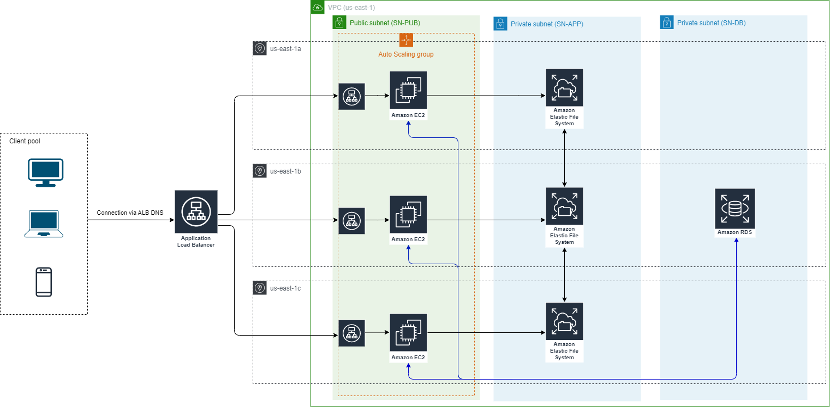
/home/ec2-user/update_wp_ip.shLaunching the EC2 instance with the template above and we can see the updated architectural diagram, with an EC2 instance provisioned in the us-east-1a availability zone and fully connected to our file system and database services.
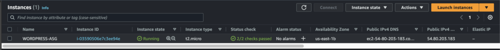
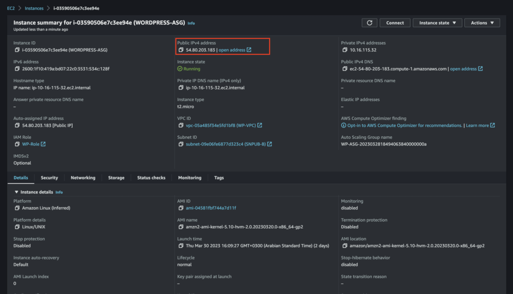
After applying the Terraform plan, we can see that Terraform creates an instance with a public IP which we can use to connect to our WordPress server.
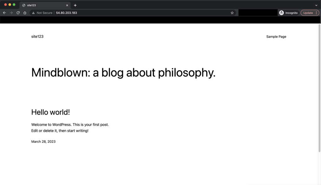
After the site initialisation steps, we have a working WordPress blog!
Now we have what looks to be a fully functional 3-tier architecture :
5. Auto Scaling Group + Application Load Balancer
At this stage, we have only one EC2 instance deployed. There are a few issues with depending on only one instance to host your application: –
- If in any case the availability zone you host the server is impaired, you lose access to that instance and have to manually deploy new instances in a different availability zone.
- If the application receives an unexpected high-traffic load (eg: major sales period/unexpectedly successful marketing campaign), the resources on the EC2 instance will be depleted, and that will hinder user experience to your site.
- And if you prepare for the top two scenarios by implementing extra EC2 instances, resources that aren’t used during low-traffic periods are wasted and you are still billed for the implementation, resulting in an increase in infrastructure cost.
Therefore, to solve the issues above, we can use an auto scaling group coupled with a load balancer to ensure that our EC2 instances are resilient across multiple availability zones and can also horizontally scale in and out to handle the varying traffic to the instances.
The auto scaling group is responsible to increase the number of instances based on a set of criterions (eg: CPU usage, network bandwidth). In this case, I just added a simple scaling structure where when the CPU usage of our EC2 instance reach more than 40%, we will add 2 additional instances. The load balancer will then perform a health-check on each of the instances available within the target group, and will automatically balance the client load among all instances. On the other hand, when the CPU load gets below 40%, the auto scaling group automatically terminates 2 of the instances and the load balancer redirects all traffic to the remaining instance.
To implement the following ALB: firstly, similar to everything we do that requires networking, a security group is required for the load balancer.
resource "aws_security_group" "SG-ALB" {
  name_prefix = "SG-ALB-"
  description = "Control access to Load Balancer"
  vpc_id      = aws_vpc.main.id

  ingress {
    description = "Allow HTTP IPv4 IN"
    from_port   = 80
    to_port     = 80
    protocol    = "tcp"
    cidr_blocks = ["0.0.0.0/0"]

  }
  egress {
    from_port        = 0
    to_port          = 0
    protocol         = "-1"
    cidr_blocks      = ["0.0.0.0/0"]
    ipv6_cidr_blocks = ["::/0"]
  }

  tags = {
    Name = "SG-ALB"
  }
}
Then, we can create the application load balancer with the subnets that our instance will reside in, followed by a load-balancing listener to provide the routing configuration and the target group of the load balancer.
resource "aws_lb" "WP-ALB" {
  name_prefix        = "WP-LB-"
  internal           = false
  load_balancer_type = "application"
  security_groups    = [var.ALB-SG-ID]
  subnets            = [var.SNPUB-A-ID, var.SNPUB-B-ID, var.SNPUB-C-ID]
}

resource "aws_lb_target_group" "WP-ALB-TG" {
  name_prefix      = "LB-TG-"
  target_type      = "instance"
  port             = 80
  protocol         = "HTTP"
  protocol_version = "HTTP1"
  vpc_id           = var.VPC-ID
}

resource "aws_lb_listener" "WP-ALB-Listener" {
  load_balancer_arn = aws_lb.WP-ALB.arn
  port              = 80
  protocol          = "HTTP"
  default_action {
    type             = "forward"
    target_group_arn = aws_lb_target_group.WP-ALB-TG.arn
  }
}
After that, we can create an auto scaling group to connect to our load balancer and attach our launch template so that every instance created by the ASG will automatically install our WordPress instance, set the necessary permissions and credentials to connect our RDS and EFS network to it, and launch the WordPress server.
resource "aws_autoscaling_group" "WP-ASG" {
  name_prefix               = "WP-ASG-"
  max_size                  = 3
  min_size                  = 1
  vpc_zone_identifier       = [var.SNPUB-A-ID, var.SNPUB-B-ID, var.SNPUB-C-ID]
  target_group_arns         = [aws_lb_target_group.WP-ALB-TG.arn]
  health_check_grace_period = 300
  health_check_type         = "ELB"
  metrics_granularity       = "1Minute"
  enabled_metrics           = ["GroupMinSize", "GroupMaxSize", "GroupDesiredCapacity", "GroupInServiceInstances", "GroupPendingInstances", "GroupStandbyInstances", "GroupTerminatingInstances", "GroupTotalInstances", "GroupInServiceCapacity", "GroupPendingCapacity", "GroupStandbyCapacity", "GroupTerminatingCapacity", "GroupTotalCapacity", "WarmPoolDesiredCapacity", "WarmPoolWarmedCapacity", "WarmPoolPendingCapacity", "WarmPoolTerminatingCapacity", "WarmPoolTotalCapacity", "GroupAndWarmPoolDesiredCapacity", "GroupAndWarmPoolTotalCapacity"]

  protect_from_scale_in = false
  launch_template {
    id      = aws_launch_template.ec2-launch-template.id
    version = "$Default"
  }
  tag {
    key                 = "Name"
    value               = "WORDPRESS-ASG"
    propagate_at_launch = true
  }
  depends_on = [var.RDS-endpoint-address, var.EFS-ID, aws_lb.WP-ALB]
}
We have to create two CloudWatch alarms to monitor and alert us when the EC2 instance hits 40% CPU usage over a certain evaluation period. As for the scaling policies, these alarms will be integrated within the scaling policy and when the alarm is triggered, instances will be created and destroyed based on the load change.
resource "aws_cloudwatch_metric_alarm" "WP_HIGH_CPU_UTIL" {
  alarm_name          = "WP_HIGH_CPU_UTIL"
  comparison_operator = "GreaterThanOrEqualToThreshold"
  evaluation_periods  = 2
  metric_name         = "CPUUtilization"
  namespace           = "AWS/EC2"
  period              = 120
  statistic           = "Average"
  threshold           = 40
  alarm_description   = "This metric monitors ec2 cpu utilization"
  dimensions = {
    AutoScalingGroupName = aws_autoscaling_group.WP-ASG.name
  }
  alarm_actions = [aws_autoscaling_policy.HIGH_CPU_ACTION.arn]
}

resource "aws_cloudwatch_metric_alarm" "WP_LOW_CPU_UTIL" {
  alarm_name          = "WP_LOW_CPU_UTIL"
  comparison_operator = "LessThanThreshold"
  evaluation_periods  = 2
  metric_name         = "CPUUtilization"
  namespace           = "AWS/EC2"
  period              = 120
  statistic           = "Average"
  threshold           = 40
  alarm_description   = "This metric monitors ec2 cpu utilization"
  dimensions = {
    AutoScalingGroupName = aws_autoscaling_group.WP-ASG.name
  }
  alarm_actions = [aws_autoscaling_policy.LOW_CPU_ACTION.arn]

}

resource "aws_autoscaling_policy" "HIGH_CPU_ACTION" {
  name                   = "HIGH_CPU_ACTION"
  scaling_adjustment     = 2 #adds two instance
  adjustment_type        = "ChangeInCapacity"
  cooldown               = 300
  autoscaling_group_name = aws_autoscaling_group.WP-ASG.name
}

resource "aws_autoscaling_policy" "LOW_CPU_ACTION" {
  name                   = "LOW_CPU_ACTION"
  scaling_adjustment     = -2 #removes two instance
  adjustment_type        = "ChangeInCapacity"
  cooldown               = 300
  autoscaling_group_name = aws_autoscaling_group.WP-ASG.name
}
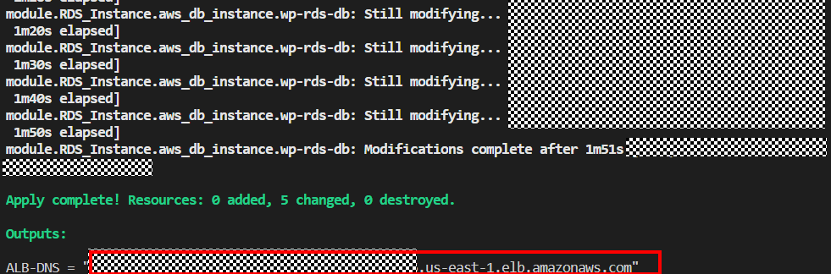
To connect to the application load balancer, we will need to connect to the DNS created by the ALB. This is the client endpoint and we will connect to this WordPress server. When the IaC creates the infrastructure, it will output the ALB DNS as shown:
We can stress the application by connecting to our instance IP and running `stress -c 2 -v -t 3000` which will simulate a high CPU load on our EC2 instance.
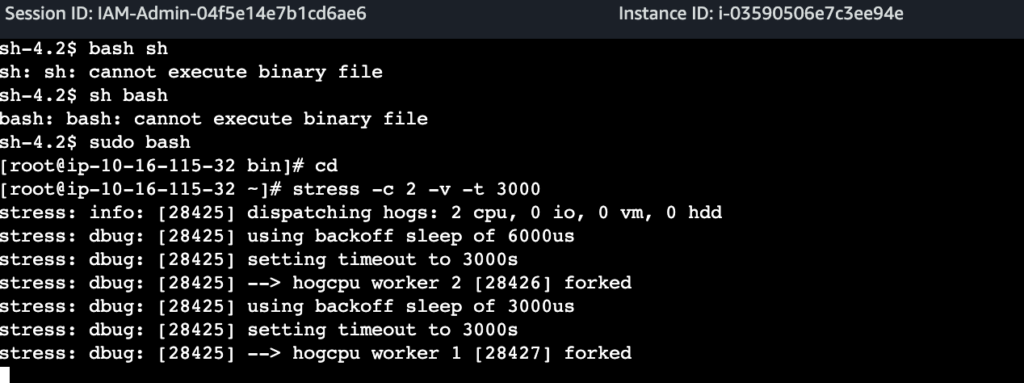
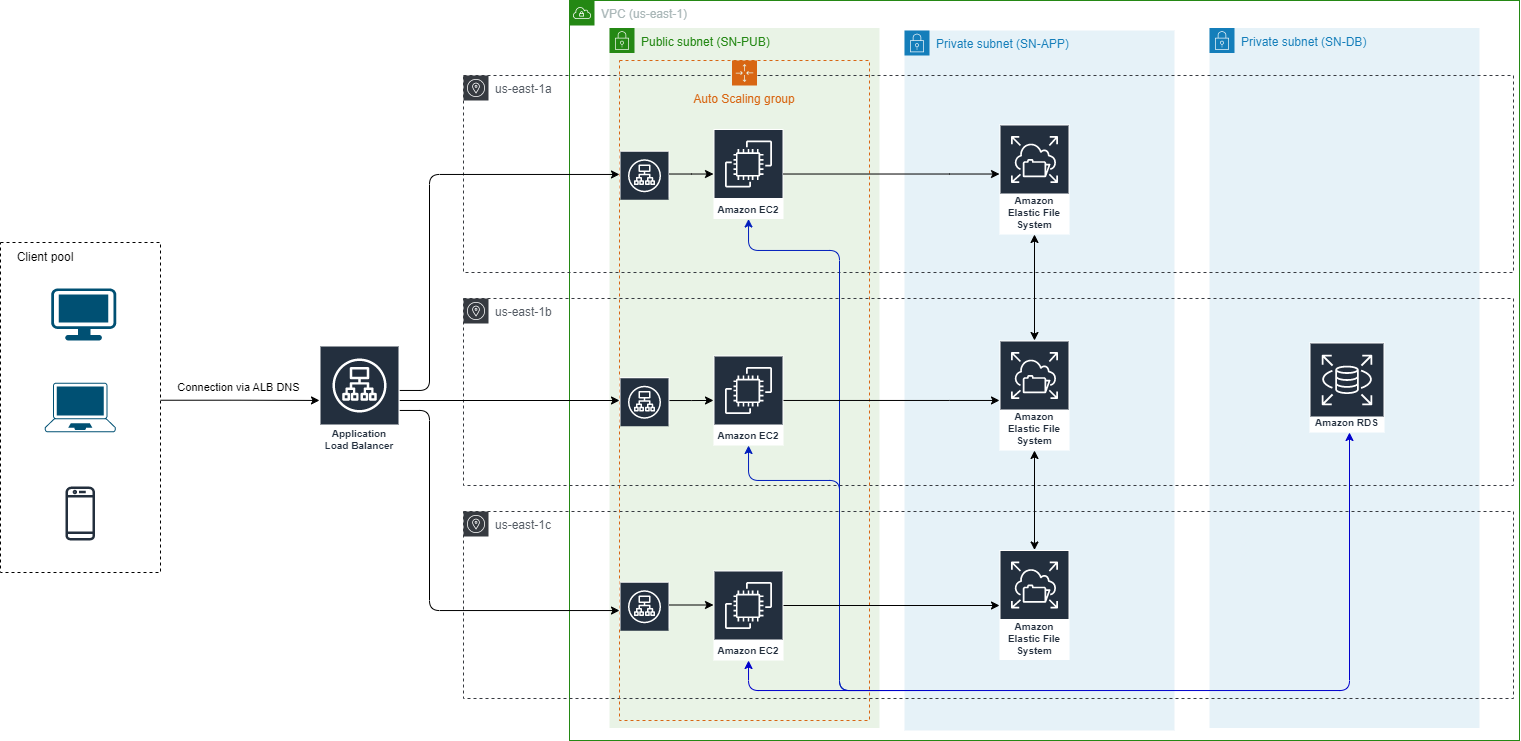
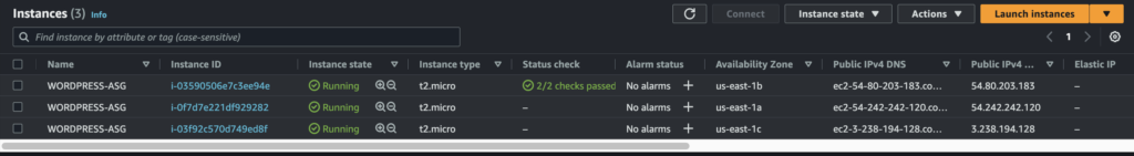
After a few minutes, we can see our auto scaling group scales out to multiple instances, all connected with an auto load balancer. Cancelling the simulated stress test will bring the CPU load down and in turn the scaling group will terminate two instance to save on resources.
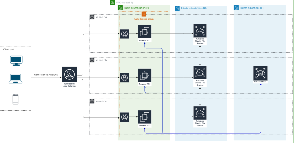
Finally, our completed architecture now looks like this. In short, we have deployed an auto scaling group coupled with a load balancer to horizontally scale our application, coupled that with an elastic file system to keep our media contents, and finally added a database system running mySql to store all our posts and user metadata.
Conclusion
That’s it! We have successfully deployed a fully elastic 3-tier WordPress server, with each tier capable of scaling independent of one another. Furthermore, by deploying the infrastructure within an IaC tool like Terraform, we can easily document the process and manage the infrastructure in a systematic manner. Again, all code and documentation can be found on the Github project page.
Thank you for reading! If you have any questions or any job opportunities in the Cloud sector, don’t hesitate to contact me via email!